Options Menu
This document provides an overview of the general options menu available in RoboDK software.
Select Tools➔
Most of the settings are stored in the computer’s user account. Changing the user account will not keep the changes applied to these settings. As an exception, the Station settings and the station parameters (available in the General tab) are stored with each Station (RDK file).
General tab
The main tab contains general options such as customizing your theme, 3D mouse navigation settings, the appearance of the tree, activate automatic backups or customize the decimal places displayed in the forms.
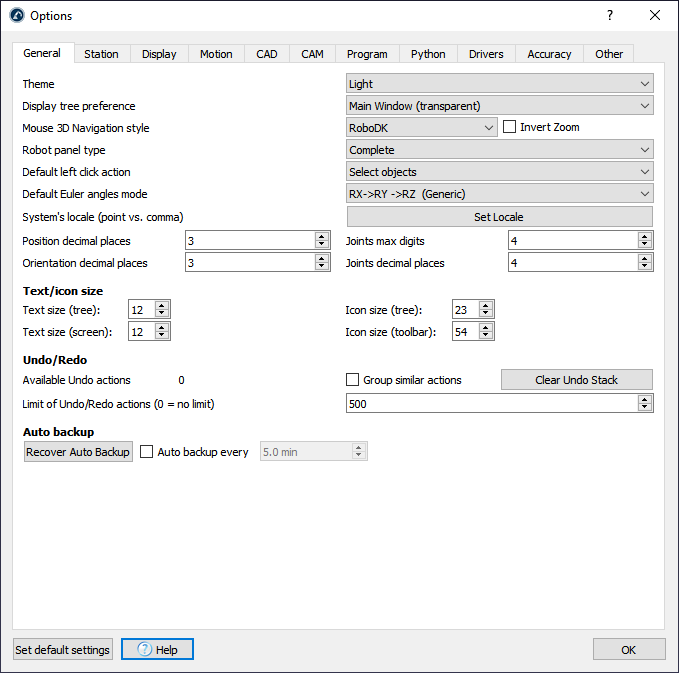
The Theme will allow you to display RoboDK in dark mode, light mode or other color modes used by default by your PC.
The default setting for Display tree preference will display the station tree inside the main window. Change it to Side Window to display the tree as a separate window.
With the Mouse 3D Navigation style, it is possible to specify the preferred type of 3D navigation with a mouse and emulate specific software, such as Rhinoceros, Catia, TopSolid or Vero software.
The Robot panel type is set to Complete by default. This will display a complete robot panel. Set this option to Normal or Basic to reduce the number of options available in the robot panel.
The Default left click action is set to select objects by default. It is possible to change it to other 3D navigation settings, for example, to rotate by default.
The Default Euler angles mode allows selecting the order in which frame rotations are done by default. A generic reference frame contains position and orientation information. Reference frames are poses and they can be represented using XYZ position and rotations around X, Y and Z. The order of rotation is very important. RoboDK will pre-select the right format/order depending on the robot that is used. See the reference frames section for more information.
System’s Locale allows setting the locale to a specific language and country. This will display the numbers in the right format and use the appropriate decimal point character.
The Position/Orientation decimal places and the Joints decimal places allow you to specify how many digits/decimals are displayed before the decimal point and after the decimal point respectively, for robot Cartesian targets and joint targets respectively.
The Text/icon size section allows changing the size of the text and icons in the tree and the toolbar.
You can Clear the Undo Stack to clear the RAM memory. It is also possible to limit the Undo/Redo actions that will be kept in memory. If RoboDK uses a lot of RAM memory or slows down it could be because there is a lot of undo actions being stored. By default, similar actions are not grouped together, for example, if a reference frame is moved, every small step will be recorded. Check Bundle similar actions together to prevent this behavior.
Station tab
The station parameters are the only parameters in the options menu that are saved with the RoboDK project (RDK file), instead of the user account settings.
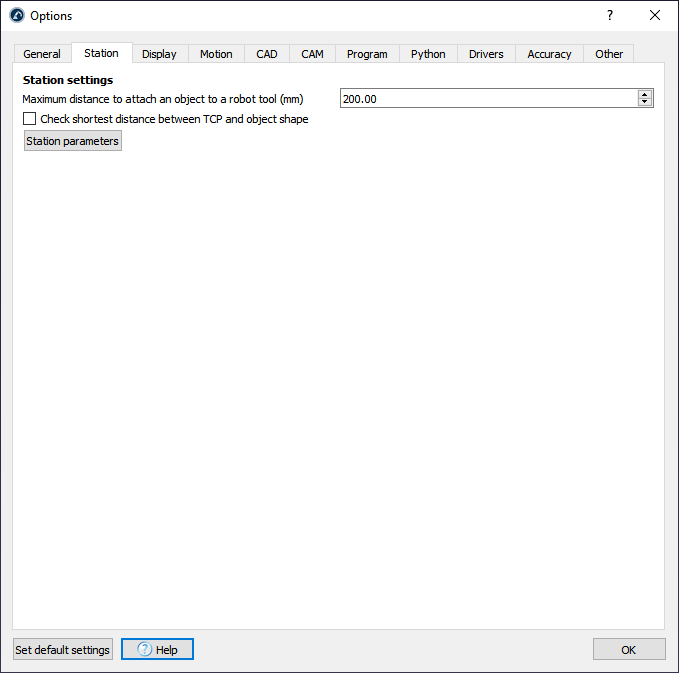
The Maximum distance to attach an object to a robot tool is used by a simulation event. Simulation events can attach objects to tools and simulate specific events. These events have no impact on generated code, they are only used for simulation purposes.
The Station parameters are state parameters that are saved with the RDK file and can be modified manually or through the API. The Station parameters allow simulating Digital Inputs and Digital Outputs and communicate the simulation with other systems through the API such as a PLC.
Display tab
The display tab allows you to customize settings related to the appearance of the 3D view.
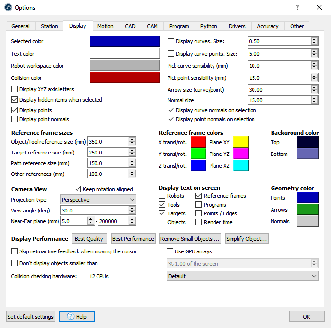
Select the colored button beside the Selected color, Text color, Workspace or Collision color to change the default colors used in the 3D view.
Select Display XYZ axes letters to display the reference frames with the corresponding X, Y, Z letters. By default, they are not displayed and the Red (X), Green (Y) and Blue (Z) colors are used respectively.
Increase the Pick curve/point sensibility to make it easier to select curves and points respectively. Alternatively, if curves or points are too close to each other and it is not easy to select them it is better to reduce these values.
Arrow size (curve/point) is the size of the green arrows displayed in curve or point follow projects (available from the Utilities menu).
Object/Target/Path/Other reference size will define the size of the frames on the screen for specific items. It is recommended to use the keys + and – instead to grow or shrink the sizes proportionally.
The reference frame colors can be updated as well as the gradient background colors manually (the plane colors are displayed when moving reference frames with the mouse).
The Camera view is set to Perspective by default. It is possible to change it to Orthographic and update some camera settings such as the View angle and the Near/Far planes.
Uncheck Keep rotation aligned to freely rotate in any direction.
By default, the display settings are set to obtain the Best Quality results. Set the Display Performance to Best Performance if RoboDK slows down because there are too many objects being displayed. This will force using the GUP and not display small objects in the screen.
It is also possible to display RoboDK on a 3D screen (use 3D view for Virtual Reality). The Stereo camera distance will define how close or far the objects feel.
Motion tab
The motion tab allows you to customize the behavior of robot simulations and the tolerances used by RoboDK to display or prevent robot singularities and collisions.
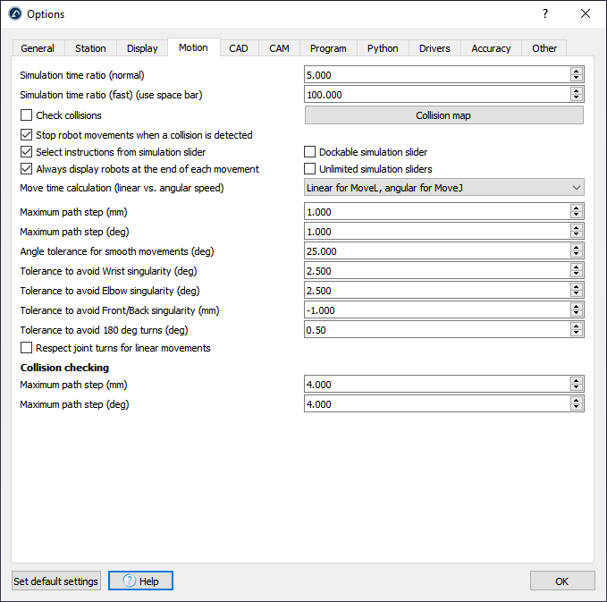
The Simulation time ratio defines how fast the simulation happens with respect to the real time. A default simulation ratio of 5 means that 1 second spent on the simulator equals to 5 seconds in real time running on the robot. More information available in the Simulation ratio section.

Check collisions and the Collision map menu allow activating/deactivating collision checking. These settings can also be changed from the tool bar or the Tools menu. By default, all programs and moving robots will be stopped if a collision is detected, uncheck Stop robot movements when a collision is detected to avoid this behavior. More information about collision map settings in the Collision tips section.
Move time calculation defines how RoboDK calculates the cycle time and how the robots use the linear/angular speeds/accelerations for simulation and timing. More information available in the Cycle Time section.
If the simulation ratio is too fast the computer might not be able to display the robot at the end of each path to keep a fast simulation. To avoid this effect: check Always display robots at the end of each movement.
The Maximum path step (mm/deg) defines how RoboDK discretizes any linear and joint movements respectively for simulation purposes.
The Tolerance to avoid Wrist singularity (deg) is the threshold angle to avoid singularity for joint 5 (deg) so it stays away from 0 deg (or when axis 4 and axis 6 are parallel). This setting applies to most 6-axis robot arms, including collaborative robots. If a singularity is detected for a robot program, the program must be changed to make sure it runs free of singularities. Lowering these tolerances will allow you to be more permissive with RoboDK but you may experience singularity warnings or errors with your real robot controller.
A similar setting is applicable to prevent the Elbow singularity (in deg) and the Front/Back singularity (in mm).
CAD tab
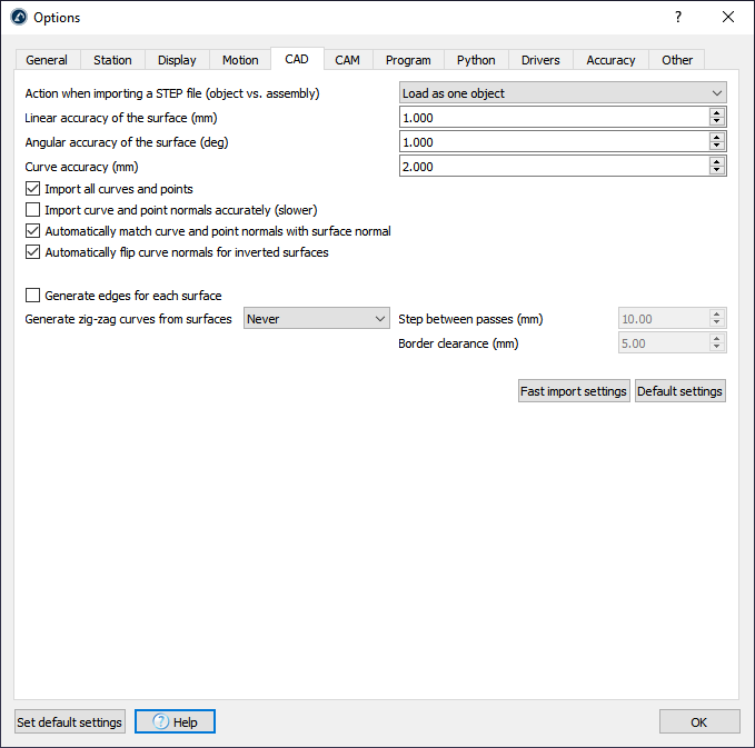
The CAD section (Computer-aided design) allows you to specify settings related to importing parametric files (STEP/STP and IGES/IGS) and displaying these files in the 3D environment.

Increase the Linear/Angular accuracy of the surface to import files faster. Decrease these values to improve the accuracy of the imported objects.
If we are using a curve or point follow project (from the Utilities menu) and we are using the Fast import settings it won’t be possible to select curves included in these types of parametric files. In that case, check the option Import all curves and points.
The Curve accuracy defines how accurate curves are imported from parametric files. By default RoboDK will import all curves included in these files. Furthermore, RoboDK will extract the edges of curves in the 3D files.
It is possible to automatically generate a zig-zag curve from each surface and specify the step between passes and how far the curve is kept from the border. This might be useful for painting or inspection applications.
CAM tab
The CAM section (computer-aided manufacturing) shows all the settings related to robot manufacturing operations, such as robot machining or 3D printing, and how to import robot toolpaths created using CAM software.

The Operation speed is the default speed used in operations for curve and point follow projects. The curve/point follow project is available in the Utilities menu.
The Approach distance for points is the default distance used to approach to points in a point follow project. This option is useful for applications like drilling or spot welding.
Include a normal approach/retract by default will include a 100 mm normal approach to the toolpath.
It is possible to ignore the Go Home command (G28 ISO code) set by some robot machining programs or set it to a specific value (XYZ coordinates).
The Program events defines what actions are taken for specific G-code events, such as setting digital outputs, managing extruder heads or triggering specific programs at different stages of the manufacturing operation.
Other options are available to define the default settings when a new robot machining project is started. These are the same settings available from the robot machining menu.
The Quick path preview section allows setting how many tools are displayed as a preview when moving the reference frame or the tool frame of a manufacturing operation.
It is possible to open the 3D printing options of the Slicer from the 3D printing section. A Slicer splits an object into a machine toolpath, then, the toolpath can be easily converted to a robot program with RoboDK.
Robot programs generated from CAM programs can be modified after they have been generated. However, updating the settings from the robot machining menu will override any previously generated program. Check Never override edited programs generated from CAM projects to avoid losing any changes.
Program tab
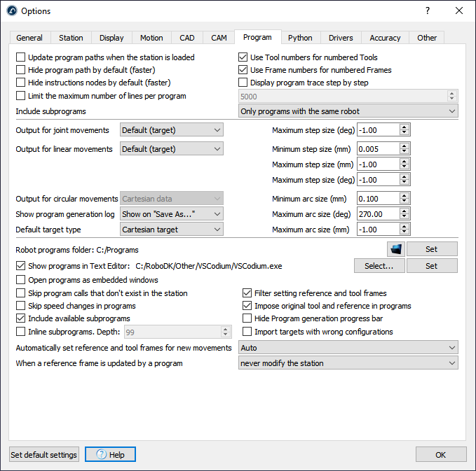
The Program tab allows you to customize settings related to robot programs and how program files are generated.
Check Update program paths when the station is loaded to recalculate robot programs. This operation will display program issues and show the programs that have issues with a warning sign 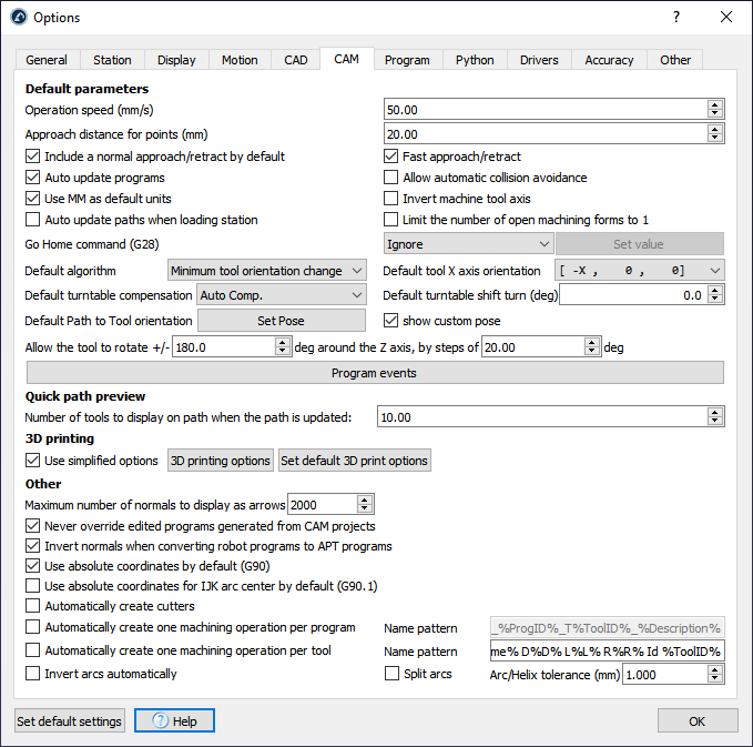
Checking Hide program path by default will not display the program paths when new programs are generated. Right click a program and check/uncheck Display path respectively to show/hide the yellow path of the robot TCP.
Use Tool/Frame numbers for numbered Tools/Frames will use the corresponding register numbers of a tool/reference frame instead of updating the tool and reference frame poses on the robot controller. This is available for robot controllers that mostly use numbered registers instead of variables. This behavior can also be customized using post processors.
It is possible to force a specific target Output for joint/linear movements on program generation, by imposing joint or Cartesian data. By default, RoboDK will use the target settings (joint coordinates for joint targets and Cartesian coordinates for Cartesian targets).
By default, RoboDK will create new targets as Cartesian targets, that means that if a reference frame is moved, the position of the robot to reach that target will be different. It is possible to select Joint targets to impose absolute targets that do not change depending on the reference/tool changes.
Select Skip program calls that don’t exist in the station to ignore generating programs.
When a reference frame is used in a program (using the Set Reference Frame instruction) and that reference is moved afterwards, the robot movement is altered. By default, the set reference frame instruction will place the robot reference at the original location without altering the station reference.
Limit the maximum number of lines per program can be checked to specify how many lines a program will have at most. This will split a long program in sub programs and will generate a main program that runs these smaller programs sequentially. Robot controllers have limited capacity and can run programs of a certain size. Except for specific/older robot controllers, most controllers can handle 5000 lines in one program.
Finally, specific settings are available for specific robot brands when using built in post processors. On the other hand, custom post processors allow customizing or imposing certain behavior right before the program is generated.
Python tab
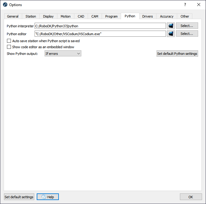
The Python tab allows you to setup the path of the Python interpreter and the Python editor used by RoboDK. Most post processors require Python to allow you to generate brand-specific robot programs. Also, some examples that use the RoboDK API require Python to be installed.
Click on Select… right beside the Python folder path to automatically display available Python interpreters. Python is required to use most robot post processors and the RoboDK API.
You can check the option Auto save station when Python script is saved to save the RDK project every time a script is saved.
We recommend you use the default settings on Windows (Python embedded and VSCodium) as shown in the image above. Alternatively, you can also use VSCode, Notepad++ or any other text editor of your choice to view or modify programs and robot Post Processors.
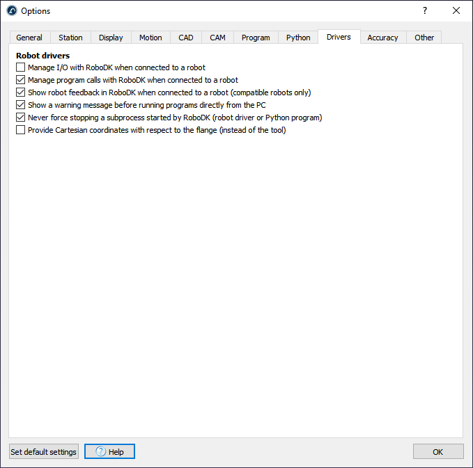
Drivers tab
The Robot drivers settings allow you to customize the behavior of robot drivers. Contrary to post processors (where programs are generated offline, then, loaded and executed on the robot), robot drivers allow you to move the robot directly from your computer.

Select Manage I/O with RoboDK when connected to a robot to simulate Inputs and Outputs as RoboDK Station Parameters instead of changing the state of Inputs/Outputs on the real robot (this is supported with some robot drivers).
The option Show robot feedback in RoboDK when connected to a robot will display the robot movement in real time as the robot moves (compatible robot drivers only).
Select Show a warning message before running programs directly from the PC to display a popup window before the program is executed from the PC (when using the Start on Robot option).
Uncheck Never force stopping a subprocess started by RoboDK if you experience problems with robot drivers. This will make sure that no other processes are running behind the scenes when a new connection to the robot created.
Accuracy tab
The Accuracy tab shows specific options related to robot calibration and robot performance testing such as ballbar testing.
Other tab
The Other tab allows you to customize settings related to the RoboDK API, activate the web server view, setup a proxy server and customize the behavior of a 3D mouse (such as 3D Connexion).
It is recommended to install FileZilla Client to transfer robot programs from the computer directly to the robot if they are both connected in the same network (most robot controllers support FTP transfer).
It is possible to allow external communication of the RoboDK API by checking Allow external API and selecting an appropriate server IP and port.
Select Activate Local Web Server view to convert your computer into a web server viewer where you can connect and see your simulations as a 3D HTML simulation.
It is possible to use a 3D Connexion mouse, such as the SpaceNavigator and change the default translation and rotation speeds using the 3D mouse.
Select Proxy settings to use a Proxy server when using Network licenses or connecting to the online library.