RoboDK Add-In for Siemens Solid Edge
The RoboDK add-in for Siemens Solid Edge allows you to combine Solid Edge’s 3D CAD modeling features with RoboDK for robot simulation, offline programming and robot manufacturing.
With the RoboDK add-in for Solid Edge you can easily load 3D models created in Solid Edge to RoboDK. This plug-in allows you to program over 1,000 robot models directly from Solid Edge designs.
Robots can be easily programmed as 5-axis machines for a wide variety of manufacturing applications such as drilling, welding, trimming, 3D printing or robot machining. More information available in the robot machining section.
The robot post processors section shows a list of the robot brands and controllers supported. It is also possible to modify or create new post processors to customize program generation.
The RoboDK Add-In for Solid Edge works with Solid Edge. You should not have any limitations using the RoboDK Add-In for Solid Edge if you already have a RoboDK license.
Install
If you have already installed RoboDK software after installing Siemens Solid Edge you should have the RoboDK plug-in for Solid Edge available in Solid Edge. The RoboDK plug-in for Solid Edge should be visible in the Toolbar.
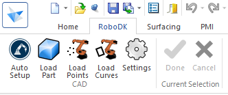
Solid Edge Toolbar
The RoboDK toolbar for Solid Edge includes 5 commands for CAD purposes.
●
●
●
●
●
The main difference between Auto Setup and Load Curve(s) or Load Point(s) is that Auto Setup loads the part and creates a new Curve/Point follow project. Using Load Curve(s) or Load Point(s) is faster and will just update the existing geometry features in RoboDK, keeping previously defined settings.
Settings
You can change the default RoboDK plug-in settings by selecting the Settings button.
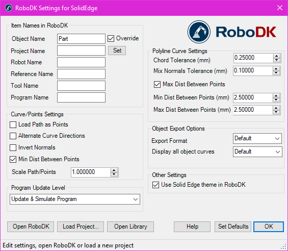
●Object Name – Set the name of the curve/points object that will be loaded in RoboDK. If this case is left blank, the name of the part or the assembly file will be used.
●Override – Override the object loaded previously in RoboDK if there is a name match.
●Project Name – Set the name/path of the RoboDK project/station (.RDK file) to use. If the file is already loaded it will use the existing project. If the open project in RoboDK does not match with the file name it will open the project if the full path is specified.
●Robot Name – Set the name of the robot that will be used in RoboDK (if you have more than 1 robot in your project). The robot name must match the name visible in the RoboDK station tree. Leave this value empty (default) to use the first or only robot available.
●Reference Name – Set the name of the reference frame to place the path with respect to the robot. The name should match the visible name in the RoboDK station tree. If a name is not provided, the active Reference Frame
●Tool Name – Set the name of the tool (TCP) to use with the robot to follow the path. The name should match the visible name in the RoboDK station tree. If a name is not provided, the active Tool Frame
●Program Name – Set the name of the program file that will be generated.
●Load Path as Points – Check this option to convert a curve into points, so a Point follow projectwill be created in RoboDK. This is useful for manufacturing operations such as drilling. Uncheck this option to load the path as a Curve follow project.
●Alternate Curve Directions - Check this option to alternate the direction of movement with each pass (Zig-Zag pattern).
●Invert Normals – Check this option to invert the calculated surface normals. This will flip the robot’s tool orientation.
●Use Solid Edge Theme in RoboDK – Start RoboDK with Solid Edge theme. This includes changing the behavior of the mouse for 3D navigation and the background color. These settings can be changed in the RoboDK menu: Tools-Options.
●Communication Port – Set the communication port to communicate with RoboDK. Multiple instances of RoboDK can be running at the same time and use different setups if a different port is used. When this value is set to -1 (default), the default port is used (20500).
●Startup Options – Set the arguments to pass to RoboDK the first time it starts. For example, to start RoboDK quietly you can set '/NOSPLASH /NOSHOW /HIDDEN'. Programs can still be generated even if RoboDK is not displayed. More information in the Command Line section of the RoboDK API.
●Chord Tolerance (mm) – Set the accuracy to split curves as a set of points.
●Mix Normals Tolerance (mm) – Set the distance tolerance used to mix normal calculations among multiple surfaces.
●Export Format – Select the export format to load the part in RoboDK.
●Display all object curves – Display the curves loaded in RoboDK even if they are not selected. You can change this setting in RoboDK (Tools-Options-Display-Display Curves).
Buttons:
●Open RoboDK – Open a project in RoboDK... A new window will open with additional options.
●Load Project … – Load the RoboDK project (RDK file) that you want to use for your current project.
●Open Library – Open RoboDK's online library.
●Set Defaults – Set the default settings for the component.
●OK – Apply these settings and close this window. Not selecting OK will not apply any settings you changed.
Examples
This section shows basic examples to generate robot simulations and programs directly from Siemens Solid Edge using the RoboDK Add-In.
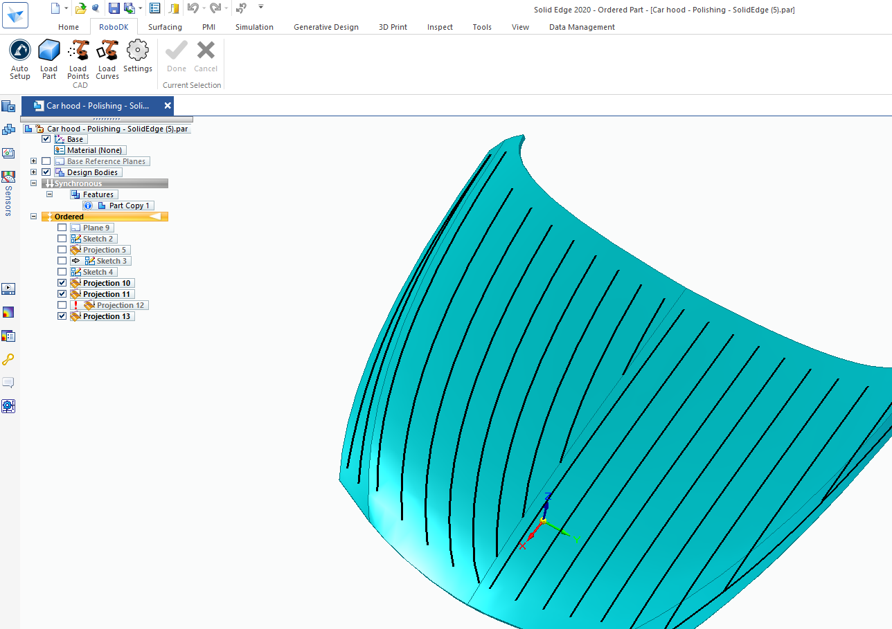
Robot Polishing
The following video tutorial shows how you can program a robot to follow a 5-axis toolpath for polishing complex surfaces using Solid Edge and RoboDK.
Manual Install
This section describes the steps to manually setup the RoboDK plug-in for Solid Edge. You should follow these steps if the RoboDK plug-in for Solid Edge was not automatically installed by default using the RoboDK installer:
1.Make sure you have Siemens Solid Edge software installed.
2.Download and install the latest version of RoboDK.
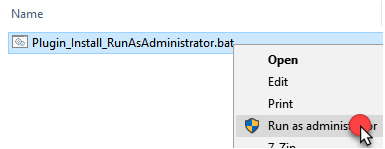
3.Locate the folder C:\RoboDK\Other\Plugin-SolidEdge\
and run the Plugin_Install_RunAsAdministrator.bat file as Administrator: Right click the BAT file and select Run as Administrator.
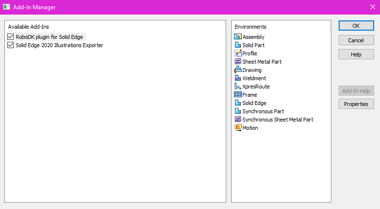
4.Select Settings➔Add-Ins from the main menu.
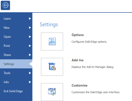
5.Activate the RoboDK plugin for Solid Edge to see the RoboDK toolbar in Solid Edge.