RoboDK TwinTool
Introduction
With RoboDK TwinTool calibration you can automatically calibrate the tool center point (TCP). Industrial robots are highly repeatable, but not accurate. Therefore, the accuracy of an industrial robot can be improved through robot and tool calibration. Without calibration, robot accuracy highly depends on the robot brand and model.
RoboDK TwinTool can be used to calibrate and validate the tool center point (TCP). The TwinTool can accurately calibrate the TCP for tools with spherical or conical geometries.
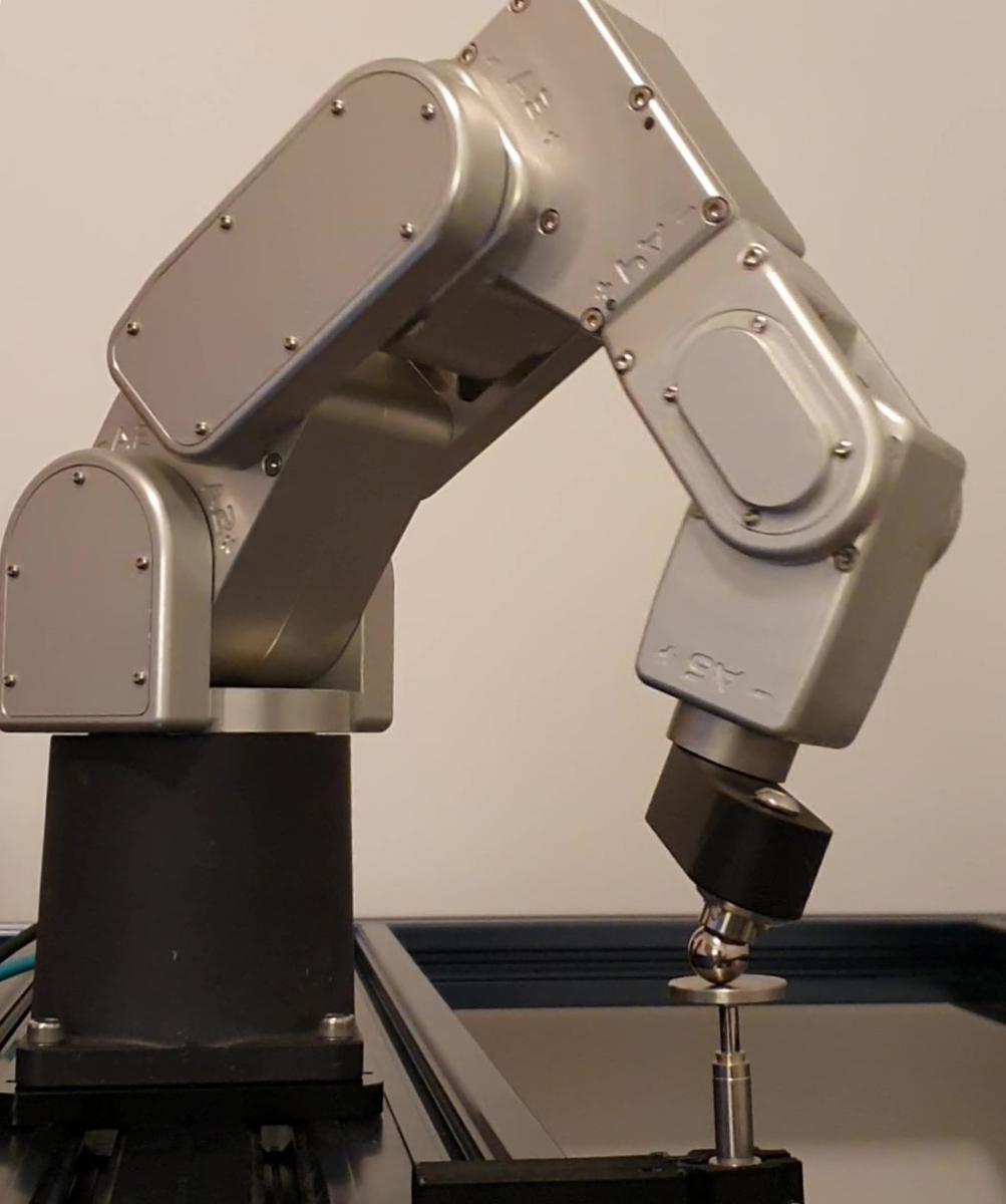
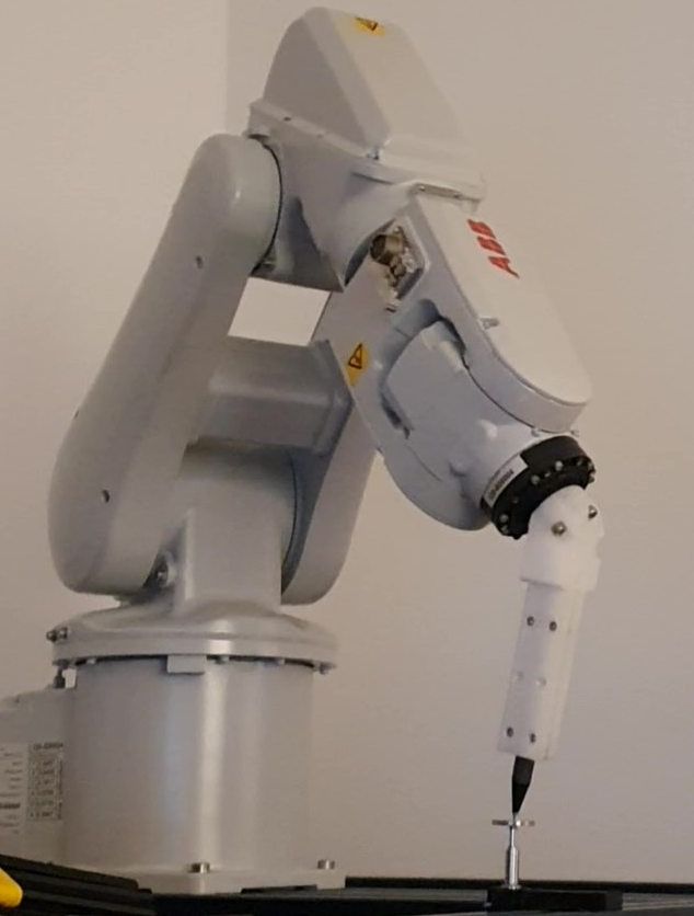
1.Spherical tools➔The center of the tool is calibrated
2.Conical tools➔ The tip of the tool is calibrated
Requirements
You must install the RoboDK TwinTool App and have a compatible sensor to perform the automated tool calibration.
Make sure to have the following:
1.One or more robot arms.
2.A compatible dial indicator (also known as LVDT or linear gage).
3.RoboDK software must be installed and an appropriate license for automated robot calibration must be available.
4.You need compatible robot drivers for your robot controller.
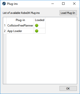
5.Install the RoboDK TwinTool App:
a.Download the RoboDK TwinTool App (contact RoboDK for a download link)
b.Double click the file to install the app and open it in RoboDK.
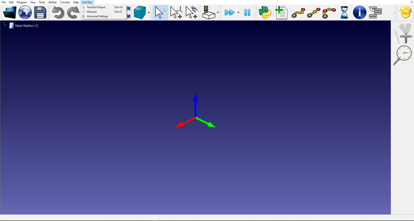
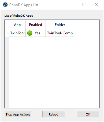
c.Select Tools➔Apps and double click on TwinTool to see the TwinTool toolbar and menu.
If you are unable to see the TwinTool app you should close RoboDK and start RoboDK again with administrator privileges to properly install the app.
Linear gage sensor
RoboDK TwinTool supports multiple linear gage sensors, including Keyence, Mitutoyo, Sylvac and others. Some communication protocols include USB, Ethernet/IP and RS232. An approximated price for an industrial grade linear gage sensor is 1,500.00 Euros.
The linear gage sensor should have an accuracy of 0.005 mm or better and a travel of 10 mm or more. It is recommended to have a measurement frequency of 50 samples per second or more. This sensor is not provided or sold by RoboDK. We recommend contacting your local distributor to supply this sensor required to use RoboDK TwinTool.
The following list shows a sample order for a Keyence linear gage:
●Keyence GT2-P12 - Pencil type gage
●GT2-UB1 - USB connection unit
●OP-87716 - Cable extension
●OP-76875 - Suggested mounting bracket for the gage
●25 mm flat contact point with M2.5x0.25 thread needed (not provided by Keyence)
The following list shows a sample order for a Mitutoyo linear gage:
●Mitutoyo 542-191 - LG 100 gage
●Mitutoyo 542-081A - EJ Counter + AC
●Mitutoyo 21HZA149 - USB interface (RS232 also supported)
●25 mm flat contact point with M2.5x0.25 thread needed (not provided by Mitutoyo)
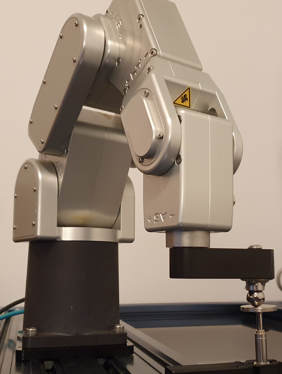
Calibration Setup
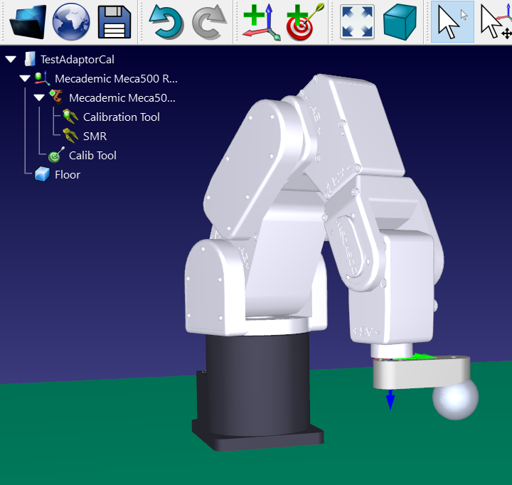
To calibrate the tool (TCP) using TwinTool you need to load the robot in RoboDK and make sure the sensor and the robot are connected. You can optionally model the cell by adding the 3D models of objects and tools. This will allow to automatically avoid collisions.
1.Load the robot:
a.Select File➔Open online library. The online library will show up in RoboDK.
b.Use the filters to find your robot.
c.Select Open to automatically load the robot in your RoboDK station.
d.Alternatively, download the robot file directly from the library (https://robodk.com/library) and open the file with RoboDK (the .robot file).
2.Connect the sensor:
a.Connect the sensor to your computer.
b.Select TwinTool➔
c.Make sure the sensor is measuring and measurements are stable.
3.Connect the robot:
a.Select Connect➔Connect robot.
b.Enter the robot IP and port.
c.Select Connect.
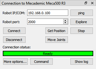
4.Select Get Position from the robot connection panel. This step will update the position of the robot in RoboDK.
Customized setup
You can optionally follow these steps to properly model the 3D environment of your cell.
1.Load the 3D model of your tool and create a tool in RoboDK. More information in the create tool section.
2.Load any 3D files to model the cell. You can load 3D STEP, IGES, STL files. More information in the getting started section.
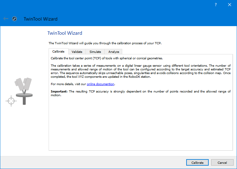
Calibration Wizard
To start the calibration procedure, simply select TwinTool➔
After launching the wizard, you will be guided through the 


Calibration Results
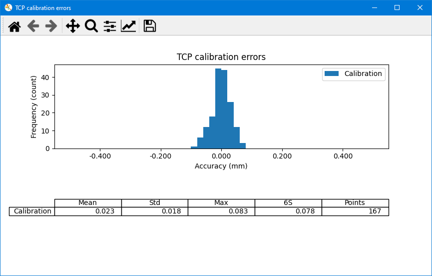
After the calibration sequence completes, you will be directed to the 
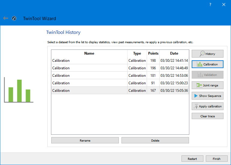
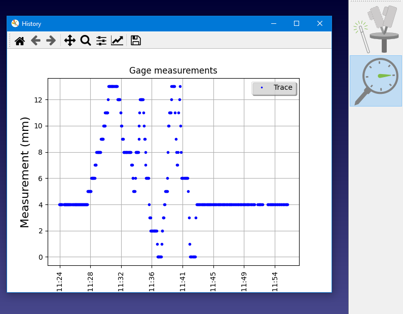
By clicking the Calibration button, you will see a chart showing the calibration results. The tool center point (TCP) is calculated using the nominal robot kinematics.
Validation
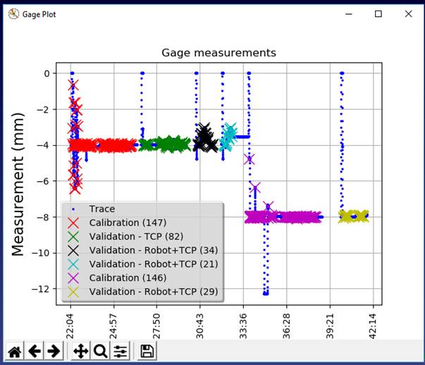
Once you have run the calibration sequence you can run some validation tests. These validation tests can be in the same location of the sensor or different locations.
Validate the tool calibration
Select
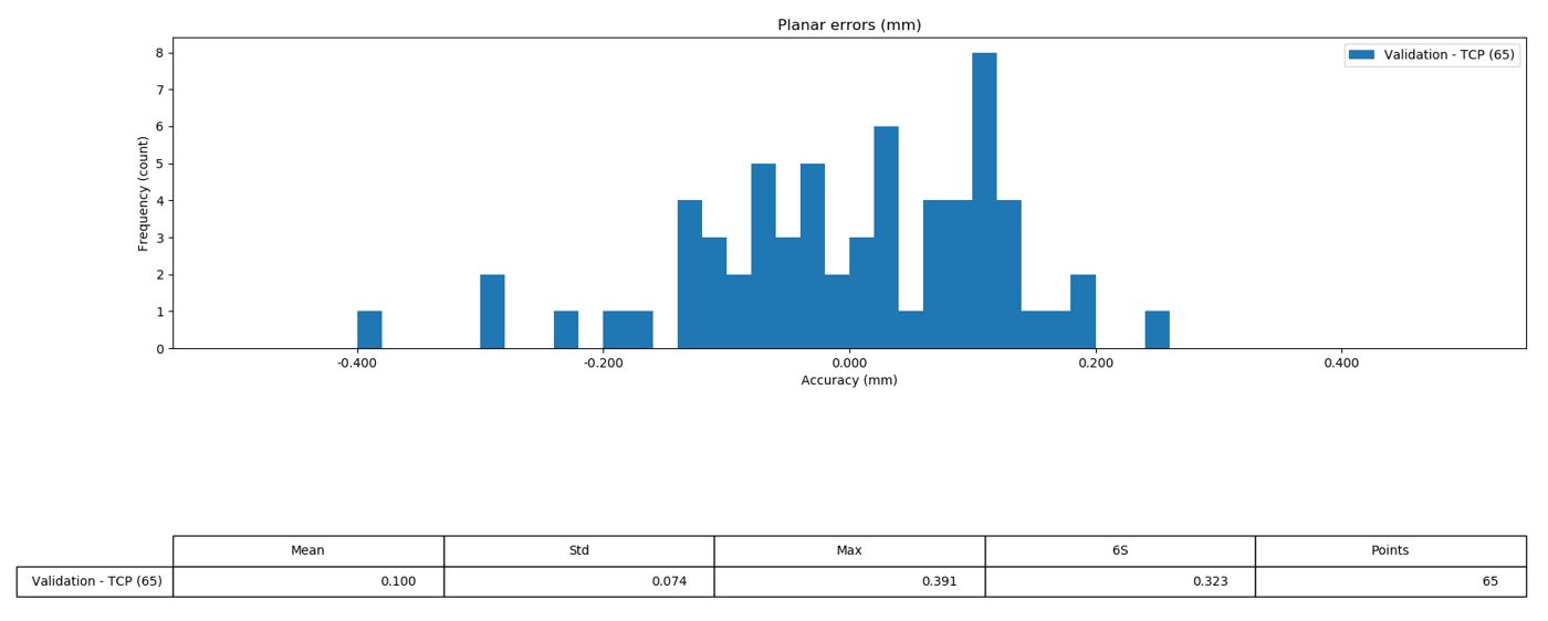
Select Validation to display a summary and some statistics about the results. These statistics correspond to the planar errors detected by the sensor.
Settings
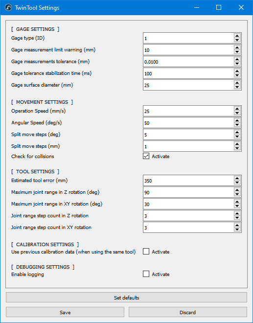
This section describes additional settings and options that you can modify to better customize your calibrations and test the robot accuracy.
Calibration Settings
Select TwinTool➔Advanced Settings to open the complete list of advanced settings. Most of these settings are prompted and set through the Wizard.