Offline setup
It is recommended to create a virtual environment of the robot setup in RoboDK (offline setup) before starting to take measurements. This section explains how to prepare the RoboDK station offline. This can be done before having the robot and the tracker, only using a computer with RoboDK installed.
RoboDK calibration project examples can be downloaded from the library of sample stations.
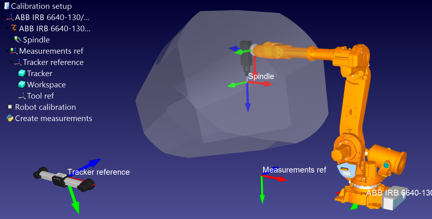
Skip this section if you already have an offline cell. The reference frames and tool frames can be estimated approximately. A sample station is shown in the following picture.
RoboDK station
A RoboDK station is where the virtual environment station and calibration information is stored. The station is saved as an RDK file. Follow the next steps to create a robot station for robot calibration from scratch (video preview: https://youtu.be/Nkb9uDamFb4):
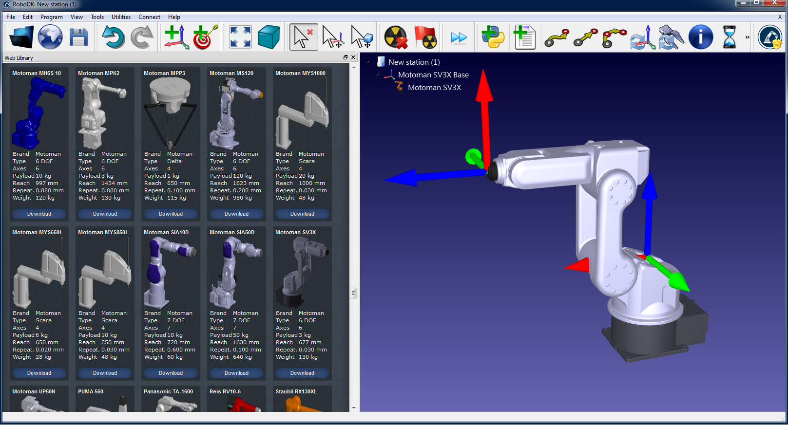
1.Select the robot:
a.Select File➔Open Robot library. The online library will open in your browser.
b.Use the filters to find your robot by name, brand, payload, ...
c.Select Open and the robot should automatically appear in your open RoboDK project.
d.Alternatively, you can download the robot files (.robot file) from http://robodk.com/library and open them with RoboDK.
1.Prepare your project for robot calibration:
a.Add reference frames by selecting Program➔Add Reference Frame.
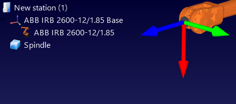
i.One “Measurements reference” frame must be added with respect to the robot base frame.
ii.One “Tracker reference” must be added with respect to the “Measurements reference” that you just added.
iii.One additional “Tool reference” can be optionally added with respect to the “Measurements reference” frame to visualize the position of the tool seen by the tracker.
Tip 1: Drag and drop items in the tree to reconstruct the dependency that exists in the real world. For example, the tracker reference must be placed with respect to the “Measurements Reference”.
Tip 2: you can approximately move any reference frames or tool frames by holding the ALT key and SHIFT+ALT key respectively. Alternatively, you can double click the reference frame and input the right coordinates.
Tip 3: Rename any object by pressing the F2 key when the item is selected in the tree.
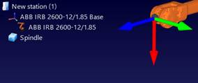
b.Add the tool object (STL, IGES and STEP files are supported formats) and drag and drop it to the robot (within the item tree), this will automatically convert the object into a tool. More information available here.
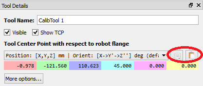
Optional: Select Program➔Add Tool (TCP) to add any TCP’s that you want to visualize in the station (to check for collisions or other). To set an approximate value of the TCP:
i.Double click the new tool.
ii.Set an approximate TCP value. You can copy/paste the 6 values at once using the two buttons at the right.
iii.It is recommended to rename the TCPs used for calibration with the name “CalibTool id”, where id is the calibration target number.
c.Add other 3D CAD files (STL, IGES, STEP, SLD, ...) to model the virtual station using the menu File➔Open… Alternatively, drag and drop files to RoboDK’s main window.
Tip 1: Import the 3D files of the measurement workspace and name it Workspace so that the robot measurements are generated inside the workspace of the tracker. Alternatively, set the workspace invisible if you do not want to constrain the measurements inside the tracker workspace. More information is available in the next section.
Tip 2: It is possible to select CTRL+ALT+Shift+P to block exporting confidential 3D files that have been imported in RoboDK.
2.Add the calibration module in the station:
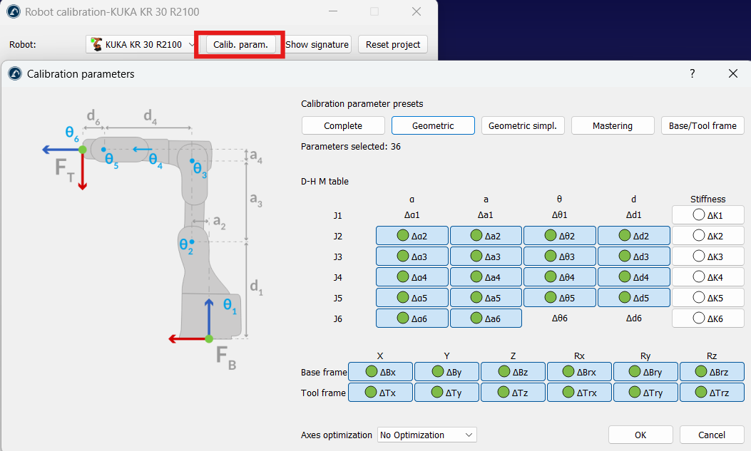
a.Select the menu Utilities➔Calibrate Robot.
b.Select Poses (6 DOF).
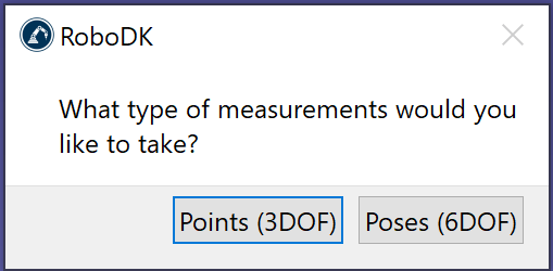
Then, the following window will appear.
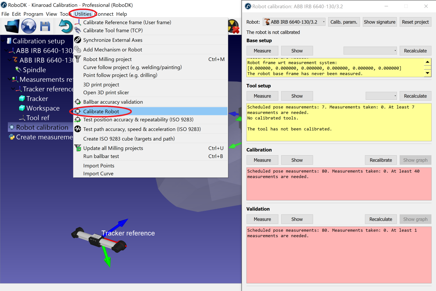
This window can be closed for now. You can open it anytime by double clicking the Robot calibration station item.
3.Save the station.
a.Select File➔Save Station.
b.Select a folder and choose a file name.
c.Select save. A new RDK file will be generated (RoboDK station file).
You can recover the station modifications anytime by opening the RDK file (double click the file).
Summarizing, it is important to double check the following points:
1.The reference frame “Measurements reference” should be directly attached to the robot base reference frame.
For now, you can use an estimate of this reference frame (approximate value).
2.The Tracker reference should be directly attached to the Measurements reference. The tracker reference must be an estimated position of the tracker measurement device with respect to the measurements reference. The base setup will find the exact position of the tracker.
3.The “Robot calibration” project is present in the station and all the measurements that you are planning to take are free of collision and visible by the tracker (double click the calibration settings and select show for each group of the four group of measurements).
4.If you want to automatically check for collisions you must use the name tag “collision” in every object that you want to use to check collisions. It is recommended to use a tool around 25% bigger than the calibrated tool to safely avoid collisions.
Generate calibration targets
There are four sets of measurements that are required to successfully accomplish robot calibration:
1.Base setup: six measurements (or more) moving axis 1 and 2 are required to place the calibration reference with respect to the robot. Select Show in the calibration settings window and the robot will move along the sequence.
2.Tool setup: seven or more measurements are required to calibrate the tool flange and the tool targets (moving axis 5 and 6). Select Show and the robot will move along the sequence.
3.Calibration measurements: 60 measurements or more are required to calibrate the robot. These measurements can be randomly placed in the robot workspace and free of collision with the surrounding objects.
4.Validation measurements (optional): as many measurements as desired can be used to validate the robot accuracy. These measurements are used only to validate the accuracy of the robot and not to calibrate the robot.
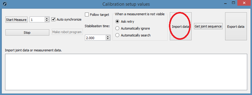
The first two sets of measurements are automatically generated by RoboDK. Select Show and the robot will follow the sequence (as shown in the following images). If the sequence needs to be changed, select Measure and export the calibration measurements as a CSV file by selecting Export data. This file can be edited using an Excel sheet and re-imported by clicking Import data.
The last two sets of measurements (calibration and validation) can be generated using the macro script called “
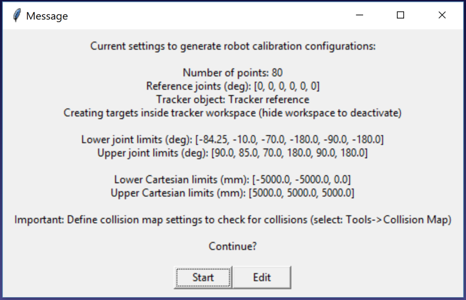
●Number of measurements: The number of measurements to generate. By default, 80 measurements are used because a minimum of 60 measurements is required for robot calibration.
●Reference position: The reference position must be a position of the robot where the tool is facing the tracker with visible targets.
●Joint limits: The lower and upper joint limits must be provided.
●Cartesian limits: You can provide Cartesian limits (X,Y,Z values) with respect to the robot reference frame.
The script automatically generates measurements where the tool is facing the tracker as well as respecting the joint and Cartesian constrains. A rotation of +/-180 deg around the tool is permitted around the direction that faces the tracker at the reference position. Furthermore, the sequence of joint movements is free of collision and inside the measurement workspace (if the workspace is set to be visible). The following image shows the summary that is presented to the user before the automatic sequence starts. It may take up to 5 minutes for the sequence to finish.
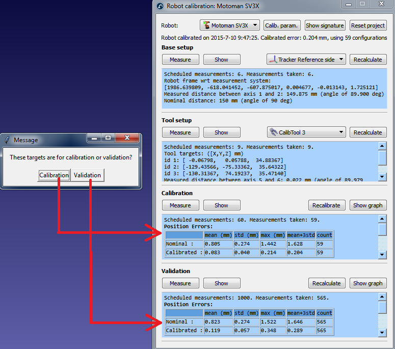
A new message will pop up once the algorithm finishes. Select Calibration to use the 60 measurements for robot calibration. You can re-execute the same script to generate another set of measurements for validation. This step is optional but 60 measurements ore more are recommended for validation purposes.
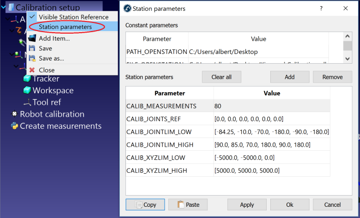
If desired, you can modify the script by right clicking the Create measurements script and selecting Edit script, then, modify additional parameters of the algorithm. The script automatically saves the user input as station parameters. You can view, edit or delete these settings by right clicking the station and selecting Station parameters, as shown in the next image.
Finally, it is also possible to import configurations that have been selected manually by selecting Import data (inside the Measure menu). You can import a CSV or a TXT file as an Nx6 matrix, where N is the number of configurations.