Probing reference frames
First, two models are required: one model of the tool and one model representing the reference frame. One model is one object defined as a list of points (X,Y,Z coordinates) corresponding to the targets with respect to the model reference (tool or base reference frame).
You must follow these steps twice to define the tool and base models:
1.Connect to VXElements by selecting Connect➔Connect Creaform’s C-Track Optical CMM.
2.Select Connect and wait until the connection is Ready.
Make sure to calibrate the tracker and the HandyProbe if it is required by VXElements. Also make sure to have the VXTrack and VXModel software options provided by Creaform.
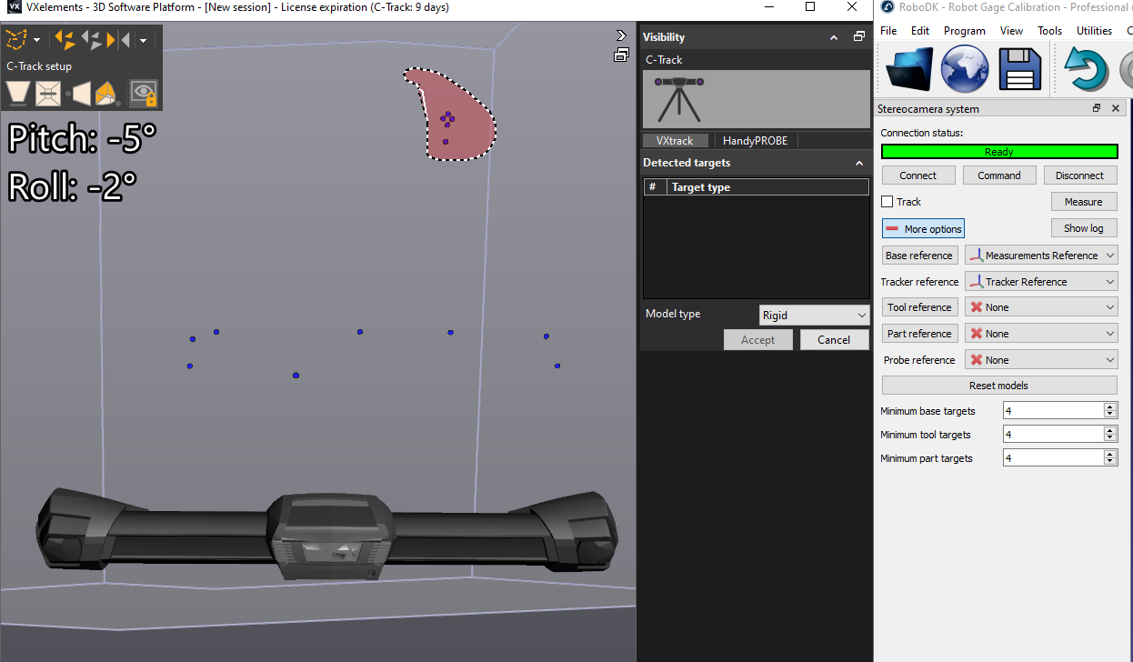
3.Select Base reference in RoboDK. VXelements will open and will display visible positioning targets. You should select the static points. Make sure to select all points that represent the static reference. You should not include points that can move.
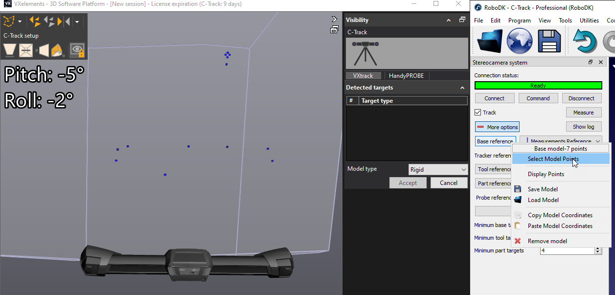
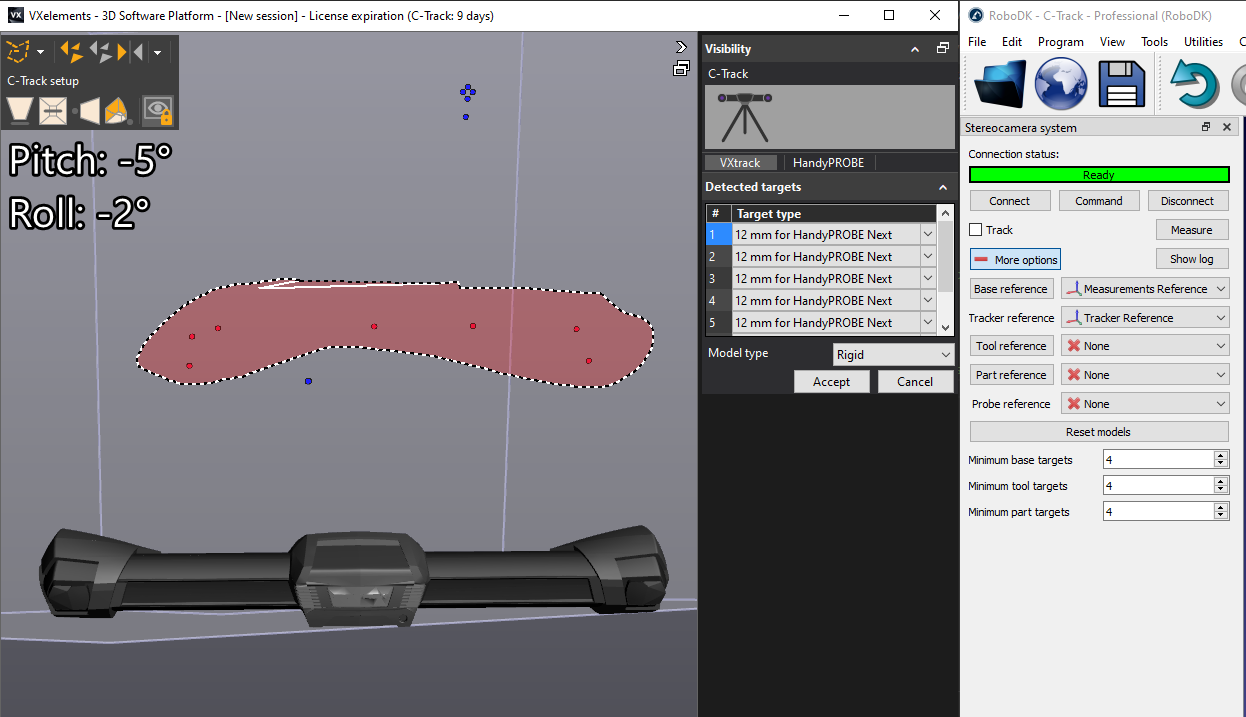
4.Select Tool reference in RoboDK and repeat this operation by selecting the points that represent the tool model.
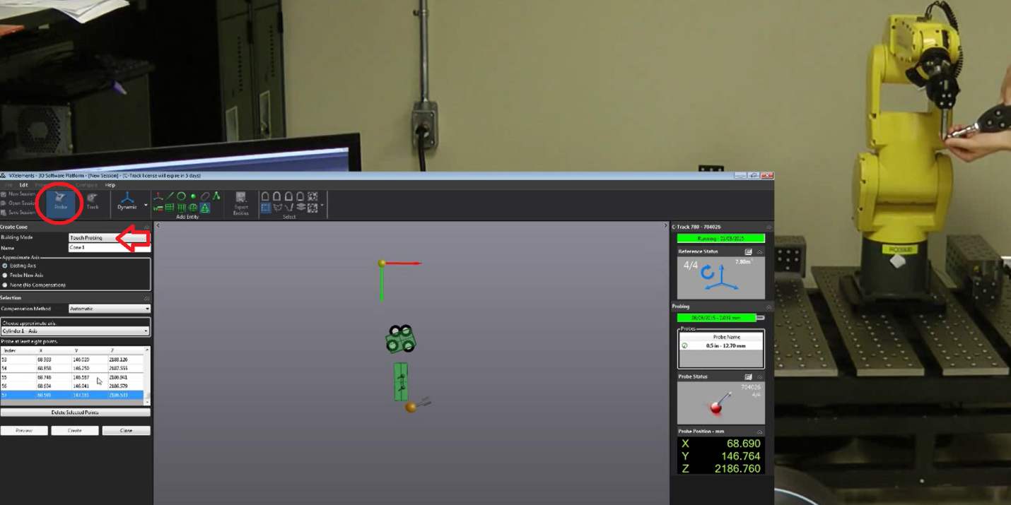
To properly move the reference frame of the object you must use the HandyProbe and bring these features in the virtual VXelements session. The model being used must be defined as the positioning model so that the features are probed with respect to this model. It is possible to probe points, lines, planes, cylinders, cones and define reference frames with respect to these features.