Robot calibration setup
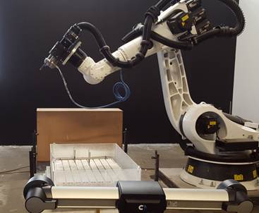
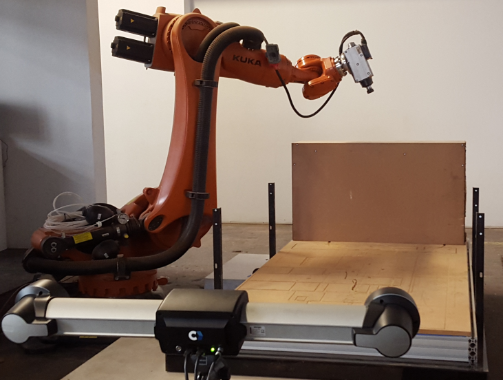
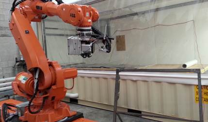
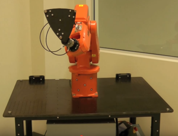
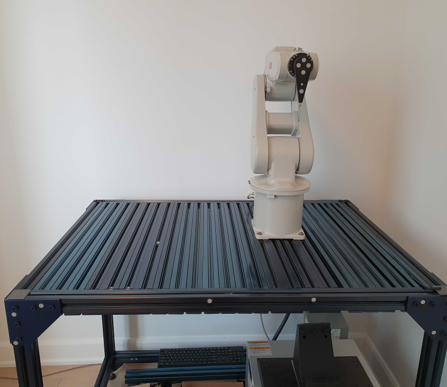
Two objects are required: a tool object (held by the robot) and a base reference object (static in the cell). The tracker must be able to see the tool object and the base reference object for each measurement. These objects are also known as “models” (in VXelements) and they are defined by a set of targets attached to the tool and reference frame objects. The tracker tracks the position of these targets providing the reference frame of these objects as a measurement with respect to the tracker. RoboDK takes each measurement as the position of the tool with respect to the base reference frame, so the tracker can be moved without altering the measurements.
It is required to attach a group of targets to the tool and the reference frame respectively to allow tracking these objects properly. The following images show some examples of appropriate setups:
The following subsections must be sequentially accomplished to be ready to start taking measurements. Finally, it will be required to connect the tracker and the robot to the computer to automate the procedure of taking measurements.
Probing reference frames
First, two models are required: one model of the tool and one model representing the reference frame. One model is one object defined as a list of points (X,Y,Z coordinates) corresponding to the targets with respect to the model reference (tool or base reference frame).
You must follow these steps twice to define the tool and base models:
1.Connect to VXElements by selecting Connect➔Connect Creaform’s C-Track Optical CMM.
2.Select Connect and wait until the connection is Ready.
Make sure to calibrate the tracker and the HandyProbe if it is required by VXElements. Also make sure to have the VXTrack and VXModel software options provided by Creaform.
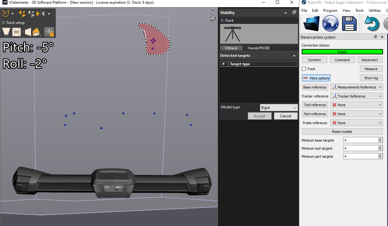
3.Select Base reference in RoboDK. VXelements will open and will display visible positioning targets. You should select the static points. Make sure to select all points that represent the static reference. You should not include points that can move.
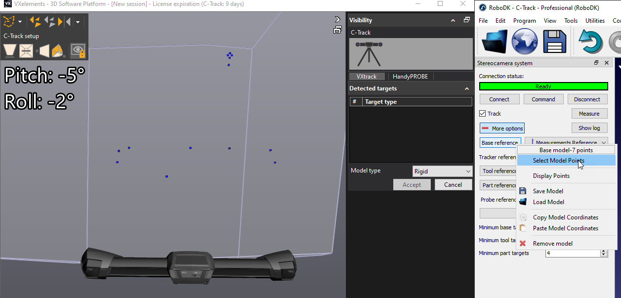
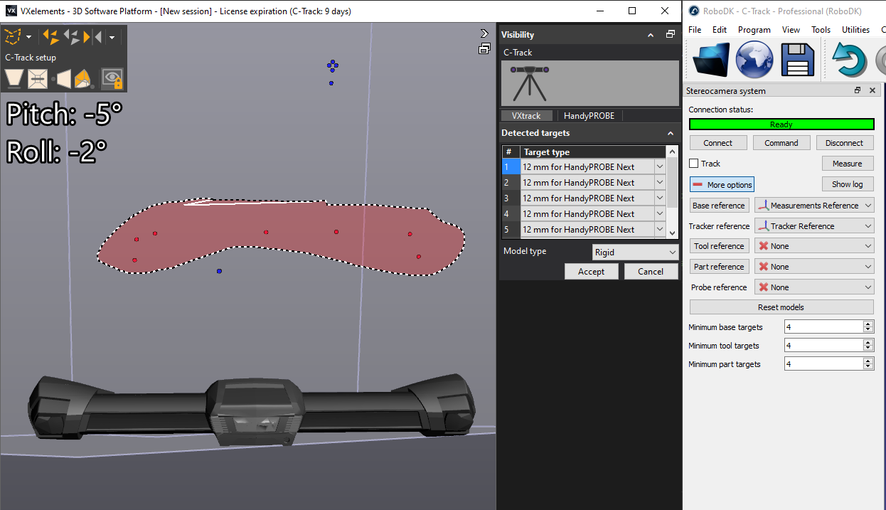
4.Select Tool reference in RoboDK and repeat this operation by selecting the points that represent the tool model.
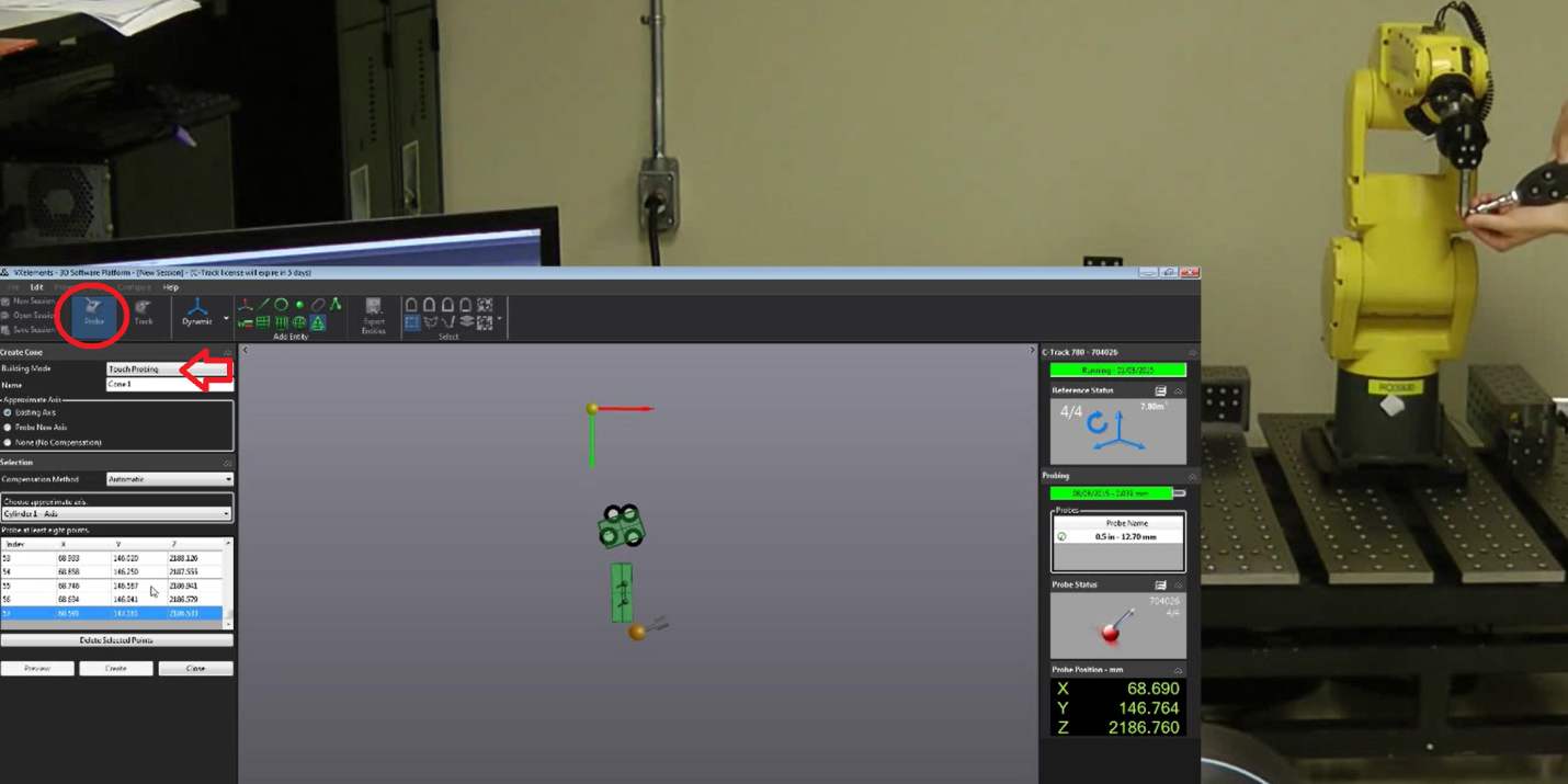
To properly move the reference frame of the object you must use the HandyProbe and bring these features in the virtual VXelements session. The model being used must be defined as the positioning model so that the features are probed with respect to this model. It is possible to probe points, lines, planes, cylinders, cones and define reference frames with respect to these features.
Connect to the tracker
The IP of the tracker is needed to properly set the communication in RoboDK. Make sure that VXelements is not running and follow these steps to verify the communication with the tracker:
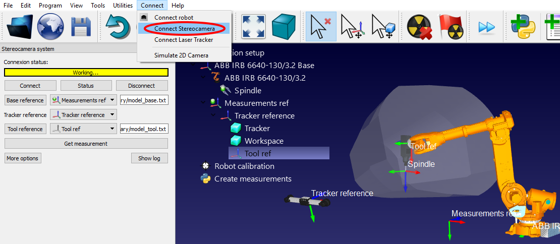
a.Select the menu “Connect➔Connect Stereocamera”. A new window should open.
b.Enter the “Base model” and the “Tool model”, as text files (generated in the previous section). These are the position of the targets that define the reference frame and the tool frame respectively.
c.Select the “Connect” button.
d.When the connection succeeds, you must provide the Base and Tool models as text files (.txt).
You will see that an integrated version of VXelements starts and, after a few seconds, you should see a green message showing “Ready” if the connection is successful. The VXelements windows can be closed and the connection will remain active. If the connection does not succeed you must make sure that no VXelements processes are running behind the scenes in the Windows Task bar or the Task manager (select CTRL+ALT+DEL to force stop the “VXelementsApiImplementation” process), then, select Connect in RoboDK to try again.
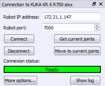
Connect to the robot
The IP of the robot (or the COM port number for RS232 connections) is needed to properly set the communication with RoboDK. Follow these steps to verify the communication with the robot:
1.Select Connect➔Connect robot. A new window will appear.
2.Set the IP and port of the robot (or the COM port if the connection is through RS232).
3.Click the Connect button.
4.Refer to the appendix if any problems arise.
If the connection is successful you should see a green message displaying Ready. The position of the virtual robot should exactly match the position of the real robot if you select Get Position. Alternatively, select Move Joints to move the robot to the current position set in the simulator. The window can be closed and the connection will remain active.