Robot Calibration (Laser Tracker)
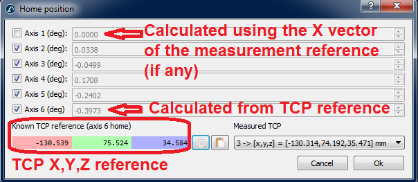
You must pay special attention if you want to recover the mastering/home values for axes 1 and 6. These values are directly related to the robot base frame for the axis 1 and a TCP reference for axis 6. Therefore, external measurements must be taken to properly set these values. This window appears after you select “Make mastering program” in the calibration menu.
The next two procedures must be followed to properly set the mastering parameters for these two axes.
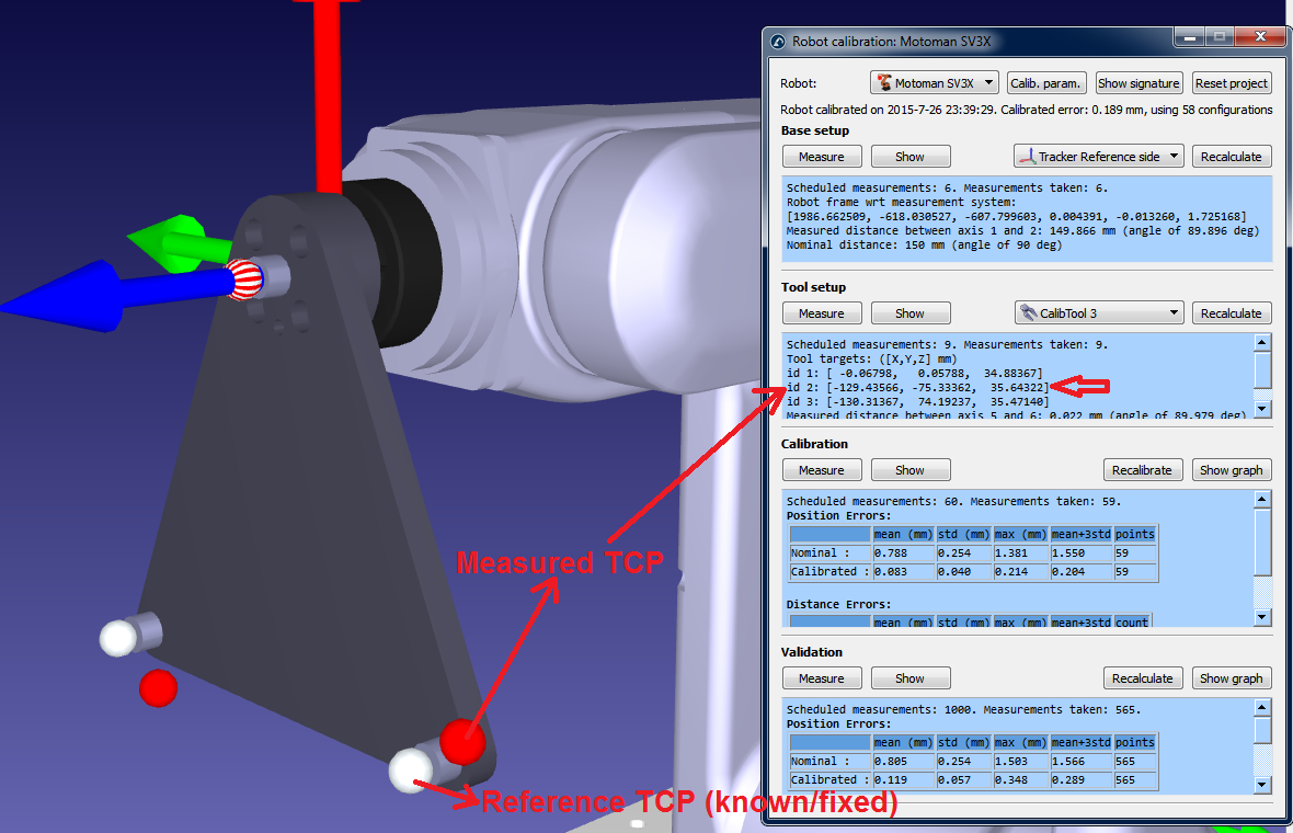
You must use a reference target to properly set the “home” position of axis 6. The angle offset will be the rotation around the Z axis of the tool flange needed to best fit the measured TCP (X,Y,Z) with the known TCP reference. The measured TCP (see the following image) is one of the TCPs that were measured in the step two of the calibration procedure. The reference TCP is a known reference that corresponds to one of the TCP for the calibration tool being used.
Ideally, the reference TCP must be measured by the CMM with respect to the tool flange (a replica of the robot tool flange would be best). Alternatively, you can use a new robot to measure (step two of the calibration procedure) the TCP for the first time and use one measured TCP as the reference. It is important to use a dowel pin and/or appropriate tool flange referencing to make sure that the end effector is always placed at the same position.
You must properly measure three base targets before starting a robot calibration if we want to align the axis 1 with the real robot base frame. These base targets must be chosen so that the reference frame can be found with respect to the robot.
The “home” position of axis 1 directly depends on the three base targets as well as the robot base setup. The robot base setup is the first calibration step, where the base frame of the measurement system is placed with respect to the robot base frame by moving and measuring axis 1 and 2.
The base targets of the measurement system can be set by pressing “Set base targets” (see following image). These are 3 measurements that will define the desired robot reference frame (the first 2 measurements define the X axis and the third point the positive Y axis). You should use appropriate reference points related to the robot base so that this procedure is repeatable.
The correction angle for joint 1 will be the angle between the X axis of the base reference measured through 3 points and the base reference measured by moving the robot axes 1 and 2. Of course, both vectors are previously projected to the XY plane of the base reference obtained by touching the tree points.
