Setup for Machining
This section shows how to prepare a simple RoboDK project, offline, for robot machining. The robot machining cell must have at least one robot, one tool (EOAT) and one reference frame (also known as coordinate system, part reference or datum). More information about building a new station in RoboDK in the getting started section.
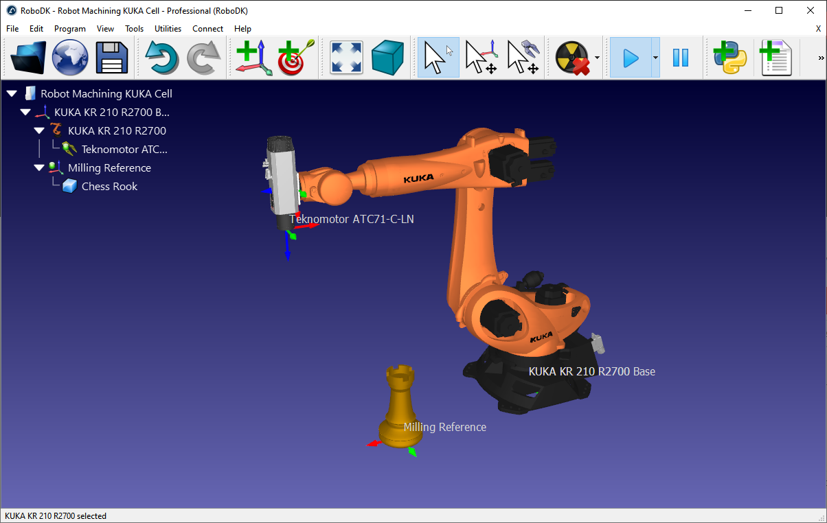
The following steps show how to prepare a robot machining setup with a KUKA KR210 robot and a Teknomotor milling spindle (this example is available in the library as Sample-New-Project.rdk).
1-Select a robot:
a.Select File➔
b.Use the filters to find your robot by brand, payload, ...
For example, select the KUKA KR210 R2700 (210 Kg payload, 2.7 m reach).
c.Select Download and the robot should automatically appear in the main screen.
2-Select a tool:
a.From the same online library, select Reset to remove the filters and filter by Type➔Tool.
b.Select Download to load a Spindle tool such as the Teknomotor ATC71-C-LN spindle.
c.The spindle will be automatically attached to the robot.
d.Close the Online library window.
3-Add a reference frame:
a.Select the robot base frame (named KUKA KR210 R2700 Base).
b.Select Program➔
c.Double click the reference and enter the coordinates:
XYZABC = [1500,1000,500,0,0,0] (mm-deg)
d.Rename the new reference frame to Milling Reference by entering a new name or by selecting F2.
4-Add the object you’ll use for robot machining (optional):
a.Select File➔
b.Select an object named Object Chess Rook.sld from the RoboDK library:
C:/RoboDK/Library
c.Drag and drop the object to the Milling Reference if it was not placed there automatically (withing the station tree)
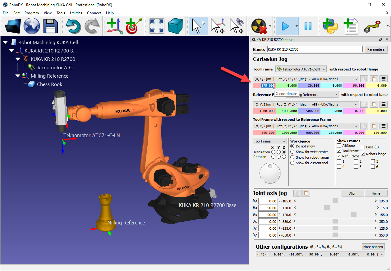
5-Double click the robot to see the robot panel (optional). The robot panel displays the active tool and active reference frame. By selecting and updating the tool and reference frame we should see the same coordinates visible in the robot controller. By default, the Teknomotor spindle has the TCP at the root of the tool holder. The tool (TCP) will have a certain length. In this example we’ll update the TCP to represent the length of the tool cutter:
a.Update the Tool X coordinate (TCP) to 375 mm. You’ll see the TCP move along the axis.
b.(optional) you could also create a second tool and define a relative TCP with respect to the first one by adding a translation along the Z axis.
c.Close the robot panel window.