Robot Manufacturing
You can use industrial robots like a machine tool (3-axis or 5-axis CNC). To achieve the same results as CNC machines, industrial robots require advanced Offline Programming software such as RoboDK to convert machine programs to robot programs. RoboDK supports converting machine programs such as APT, G-code ACL, TAP or NCI to robot simulations and robot programs.
Robotic machining includes different material removal applications, such as milling, drilling, chamfering, and deburring, typically performed by automated machine tools (CNC).
The part dimensions are defined using computer-aided design (CAD) software, and then translated into manufacturing programs (such as G-code) by computer-aided manufacturing (CAM) software. The manufacturing programs can then be converted to robot programs using RoboDK’s Offline Programming tools.
Additional axes, such as a turntable and/or a linear rail can be created and synchronized with the robot to extend the workspace.
Robot Machining Examples
This section shows some examples that involve robot machining. Some of these examples include using a plug-in to show how to generate the CAM toolpath. However, you can load any generic 5-axis toolpath in RoboDK such as APT, NC or G-code files.
Learn more about example projects in the examples section.
Visit the CAM Add-Ins section of our documentation for more examples on robot machining projects, such as Mastercam, MecSoft/RhinoCAM, Inventor, FeatureCAM or Fusion 360.
Getting started with Robot machining
This example will help you understand the basics of robot machining in RoboDK and how to convert a 3-axis robot machining job to a robot machining simulation and robot program.
Learn more about this robot machining example.
Getting started with Robot machining (5x)
This example will help you understand how you can configure robot machining settings in RoboDK and how to convert a 5-axis robot machining job to a robot machining simulation and robot program.
This example will also help you create a safe approach/retract movements between different machining job operations.
Learn more about this example.
Robot machining with external axes
This example shows how to use a KUKA robot with 3 additional external axes for robot machining. The cell includes a 6-axis robot arm, a one axis rail and a 2-axis turntable.
More information available in the RhinoCAM examples section. The integration between RhinoCAM and RoboDK automatically loads APT files from RhinoCAM to RoboDK.
Laser cutting
This example shows how to use a Yaskawa/Motoman robot for a laser cutting application. The robot cutting toolpath is defined using the RoboDK Add-In for Autodesk Fusion.
Learn more about this laser cutting example.
Robot Mold Machining
This example shows how to use a Yaskawa/Motoman robot for robot machining and the RoboDK Add-In for Mastercam. RoboDK supports automatically loading NCI or NC files generated by Mastercam.
Visit the :FCAMExample3x for more information.
Learn more about this mold machining example.
Robot deburring
This example shows how to use an ABB robot for deburring. This example includes a pick and place operation.
Learn more about this plastic deburring example.
Polishing
This example shows how to use a KUKA robot for polishing.
Learn more about this plastic deburring example.
Setup for Machining
This section shows how to prepare a simple RoboDK project, offline, for robot machining. The robot machining cell must have at least one robot, one tool (EOAT) and one reference frame (also known as coordinate system, part reference or datum). More information about building a new station in RoboDK in the getting started section.
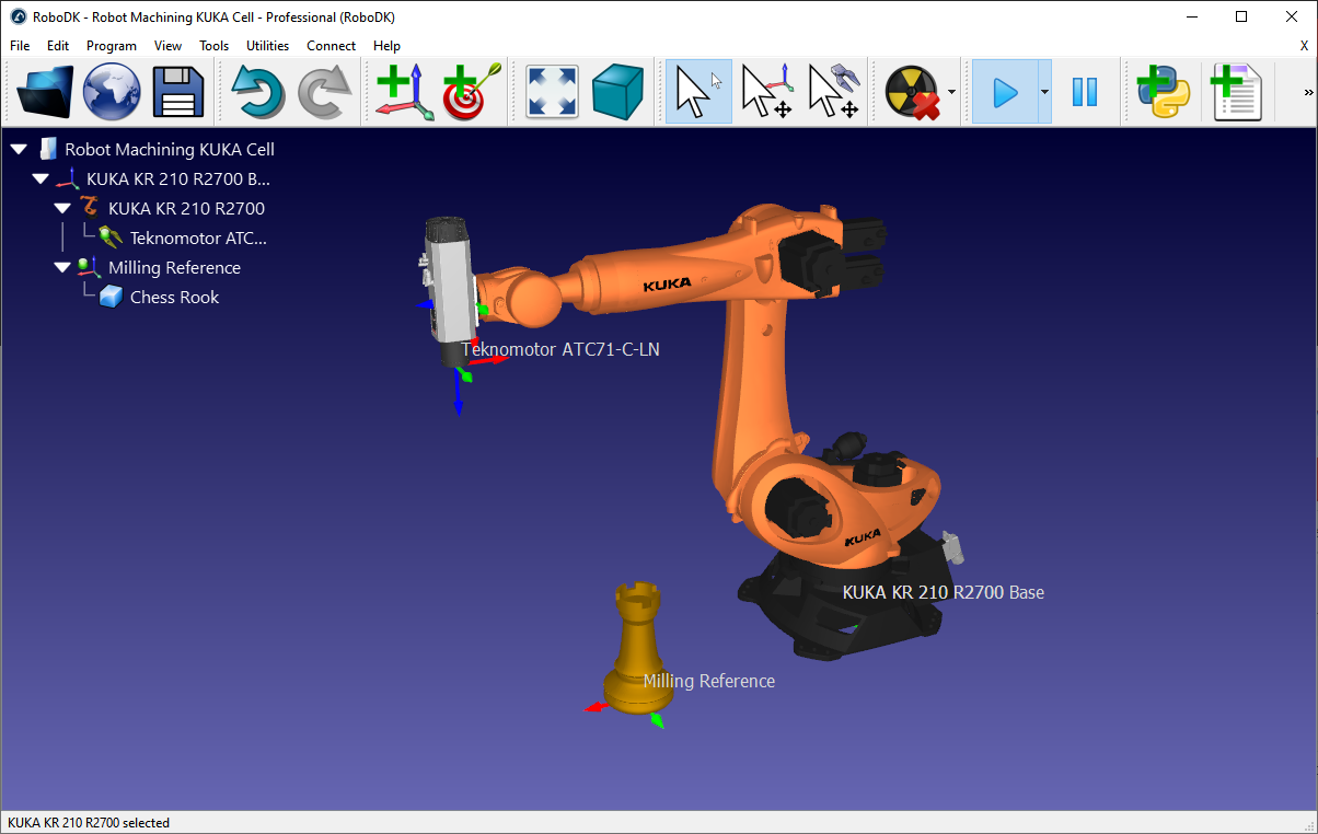
The following steps show how to prepare a robot machining setup with a KUKA KR210 robot and a Teknomotor milling spindle (this example is available in the library as Sample-New-Project.rdk).
1-Select a robot:
a.Select File➔
b.Use the filters to find your robot by brand, payload, ...
For example, select the KUKA KR210 R2700 (210 Kg payload, 2.7 m reach).
c.Select Download and the robot should automatically appear in the main screen.
2-Select a tool:
a.From the same online library, select Reset to remove the filters and filter by Type➔Tool.
b.Select Download to load a Spindle tool such as the Teknomotor ATC71-C-LN spindle.
c.The spindle will be automatically attached to the robot.
d.Close the Online library window.
3-Add a reference frame:
a.Select the robot base frame (named KUKA KR210 R2700 Base).
b.Select Program➔
c.Double click the reference and enter the coordinates:
XYZABC = [1500,1000,500,0,0,0] (mm-deg)
d.Rename the new reference frame to Milling Reference by entering a new name or by selecting F2.
4-Add the object you’ll use for robot machining (optional):
a.Select File➔
b.Select an object named Object Chess Rook.sld from the RoboDK library:
C:/RoboDK/Library
c.Drag and drop the object to the Milling Reference if it was not placed there automatically (withing the station tree)
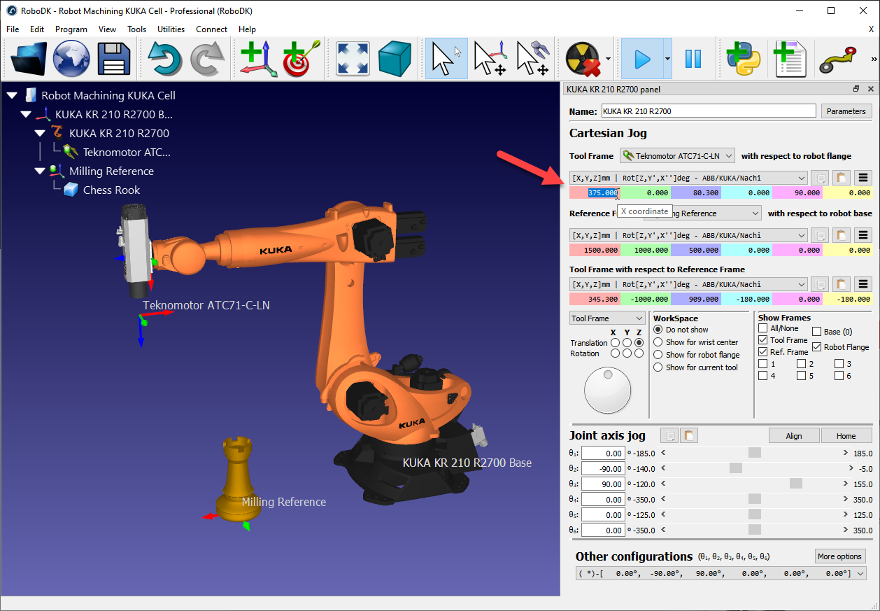
5-Double click the robot to see the robot panel (optional). The robot panel displays the active tool and active reference frame. By selecting and updating the tool and reference frame we should see the same coordinates visible in the robot controller. By default, the Teknomotor spindle has the TCP at the root of the tool holder. The tool (TCP) will have a certain length. In this example we’ll update the TCP to represent the length of the tool cutter:
a.Update the Tool X coordinate (TCP) to 375 mm. You’ll see the TCP move along the axis.
b.(optional) you could also create a second tool and define a relative TCP with respect to the first one by adding a translation along the Z axis.
c.Close the robot panel window.
Robot Machining project
Follow these steps to set up a new robot machining project in RoboDK given an NC file generated using CAM software (such as G-code or APT):
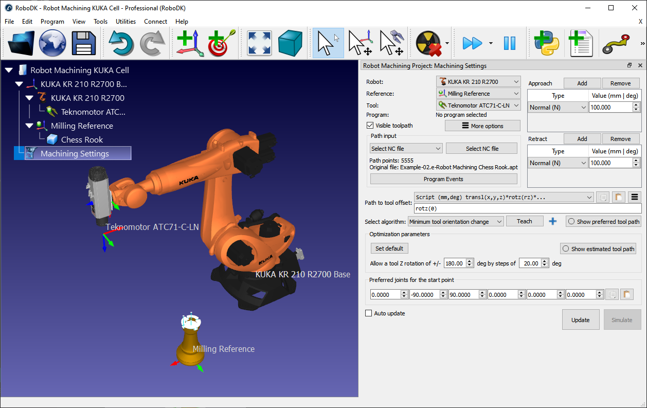
1.Select Utilities➔
A new window will pop up, as shown in the image.
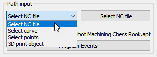
2.Select Select NC file in the Path input section
3.Provide an NC file, such as the following APT machining file:
C:/RoboDK/Library/Example-02.e-Robot Machining Chess Rook.apt
4.Rename the robot machining project to Machining Settings by right clicking the new item in the tree and selecting Rename (F2).
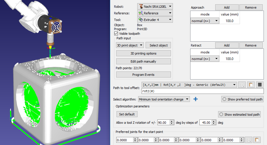
Select the robot, the reference frame and the tool in the top left section of the menu, as shown in the following image. The toolpath should be displayed in green with respect to the correct coordinate system.
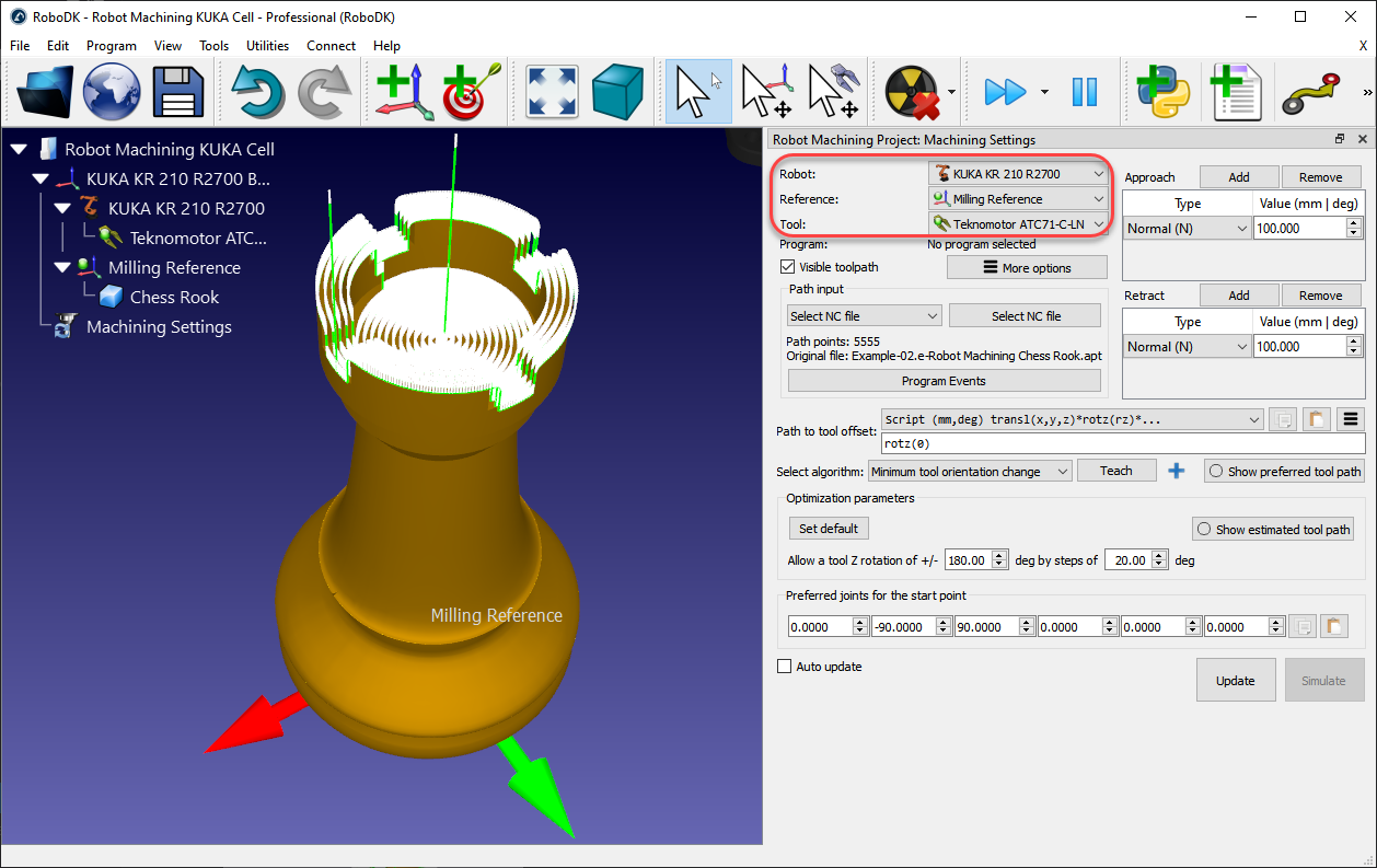
The machining toolpath is displayed in Green and the path normals are shown in white vectors. Uncheck Visible toolpath to hide the toolpath.
You can select Update to see if you can create a robot machining program with the default settings. If the program was generated successfully, you’ll see a green check mark. You can then select Simulate or double click the generated program to see the simulation start.
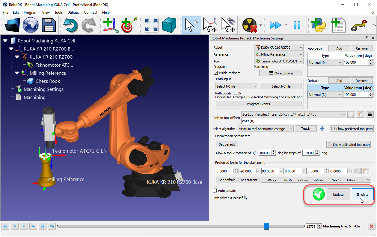
If you see a red cross with a warning message it means that your robot machining program is not feasible. You may have to change some settings such as the tool orientation, the optimization parameters, the start point or the location of the part.
The following sections provide more information about how to customize the robot machining settings.
Path input
The path input allows you to select different ways to provide a toolpath.
●Select NC file: As one NC file (obtained from CAM software), as described in this section.
●Select curve: As one or more curves, as described in the Curve Follow Project Section.
It is possible to import curves as a list of coordinates in RoboDK.
●Select points: One or more points, as described in the Point Follow Project Section.
It is possible to import points as a list of coordinates in RoboDK.
●3D print object: As an object for 3D printing. A slicer is used to convert the geometry to a toolpath
Program Events
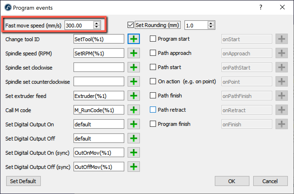
Select Program Events to display special events that need to be taken into account when generating robot programs. This includes triggering a tool change, setting the spindle speed in RPM or triggering specific programs on program start or program finish.
You can specify a rounding valuein Program events. This will automatically create a rounding instruction at the beginning of your program and will help making the robot machining programs smoother, preventing the robot to shake. For example, on an ABB robot this will set the ZoneData value in mm, on a Fanuc robot this will set the CNT value as a percentage and on Universal Robots controllers it will set the blending value in mm.
If you are using G-code or NCI files, custom M codes will be triggered by default as function calls to M_RunCode (the M code is passed as a parameter). You can remove the custom M calls by deleting the call to M_RunCode.
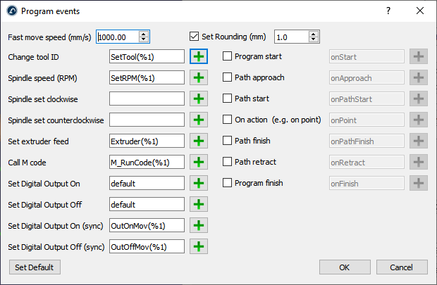
Move your mouse cursor over the corresponding field for more information to customize each section.
For example, when changing the tool you can use the %1 value to represent the tool ID provided by your CAM software. If you prefer triggering static functions instead of passing arguments you can replace SetTool(%1) by SetTool%1. When using tool 2, this would generate SetTool2 instead of SetTool(2).
Approach/Retract
You can customize your approach and retract movements from the top right of the robot machining menu. By default, RoboDK adds approach and retract movements of 100 mm along the normal.
Select Add to add an additional retract movement. The green path will be updated accordingly. It is possible to select among moving along a specific axis, provide coordinates, having an arc approach, etc. You can also combine multiple approach/retract movements by selecting the Add button.
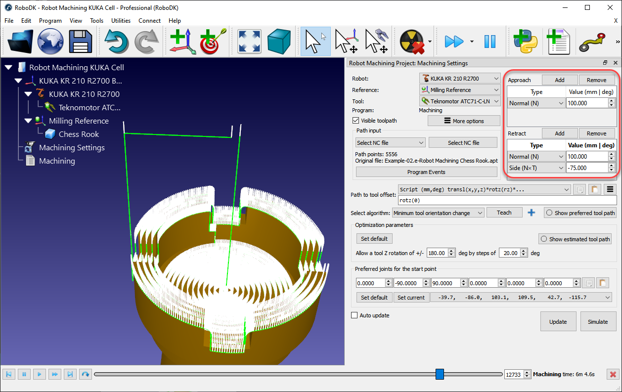
Select Remove to remove a specific approach or retract movement.
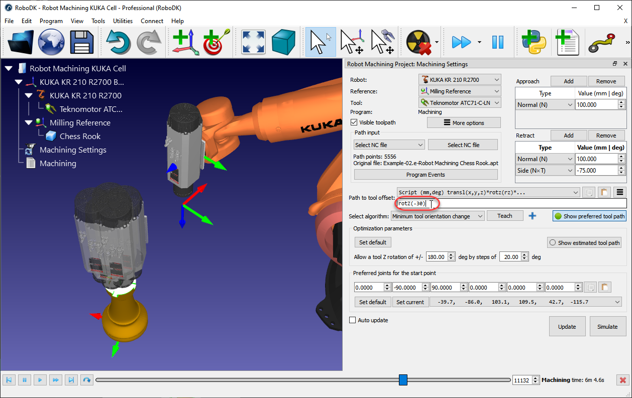
Path to tool offset
The path to tool offset allows changing the preferred orientation of the tool along the toolpath. This option is mainly used to turn the tool around the Z axis of the TCP. This allows handling the 6th degree of freedom around the tool axis. Several options are offered depending on the application and its requirements. For example, you can choose to minimize the tool orientation or follow the tool orientation along the path.
Since a 6-axis robot is used to follow a 3-axis or 5-axis CNC manufacturing program we have an additional degree of freedom to define. This degree of freedom is usually the rotation around the Z axis of the TCP. This additional degree of freedom is especially useful to avoid singularities, joint limits, collisions or reachability issues.
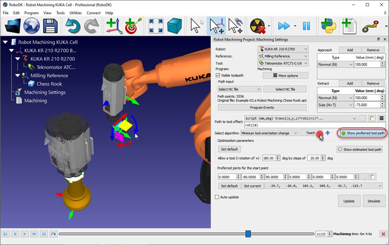
By default, the path to tool offset displays a rotz(0) transformation. This means you can add an additional rotation around the Z axis of the tool. This value can be modified to establish the preferred orientation of the tool, modifying the orientation around the Z axis of the TCP or in combination with other axes. The preferred orientation is the orientation the robot will try to keep while following the toolpath.
By default, RoboDK uses the Minimum tool orientation change algorithm. This means the orientation of the tool is kept as constant as possible along the toolpath. In general, this option is suitable for milling operations as it minimizes robot joint movements. Alternatively, other algorithms/methods are available, such as the tool orientation following the toolpath (useful for cutting applications, where the blade needs to remain tangent along the path), or the robot holding the object if the toolpath needs to be followed attached to the robot tool (for example, for dispensing or polishing applications, also known as Remote TCP configurations).
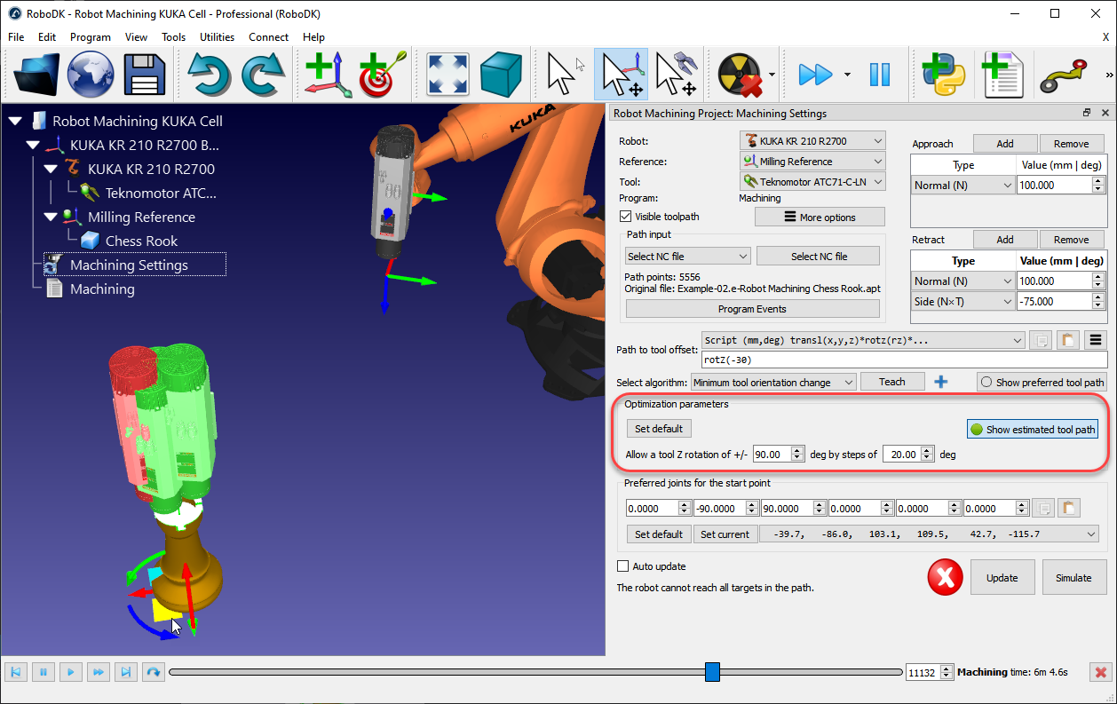
Optimization parameters
Given a preferred tool orientation, the robot can have a certain freedom to turn around the Z axis of the tool. This allows the robot to solve the program avoiding robot singularities, joint limits and making sure all points are reachable. By default, RoboDK allows the tool to rotate up to +/-180 degrees around the TCP axis by increments of 20 deg.
It is recommended to constrain this rotation depending on the application. For example, it is possible to enter +/-90 degrees to constrain the allowed rotation by half. Decreasing this parameter will also reduce the processing time to obtain the program.
If some points of the path are not reachable, it is recommended to rotate the reference frame or to be more permissive with the tool Z rotation. The reference frame can be moved by holding the Alt key and dragging the coordinate system to better fit the part inside the robot workspace.
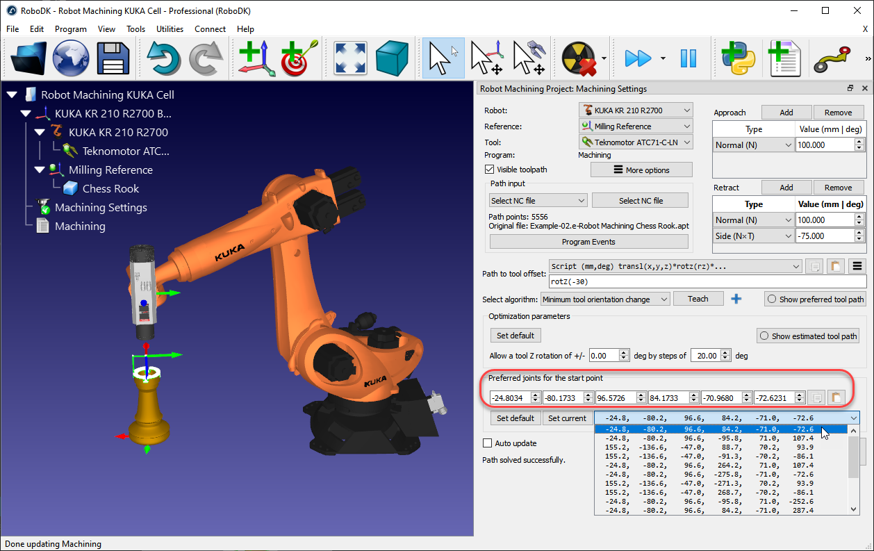
Preferred Configuration
RoboDK automatically selects the start configuration that is closer to the preferred start joints (Preferred joints for the start point). From that point, the robot will follow linear movements, so the robot configuration will not change.
A dropdown menu will display all the possible solutions to start the program. If required, select a preferred robot joint configuration, and select Update to recalculate the program.
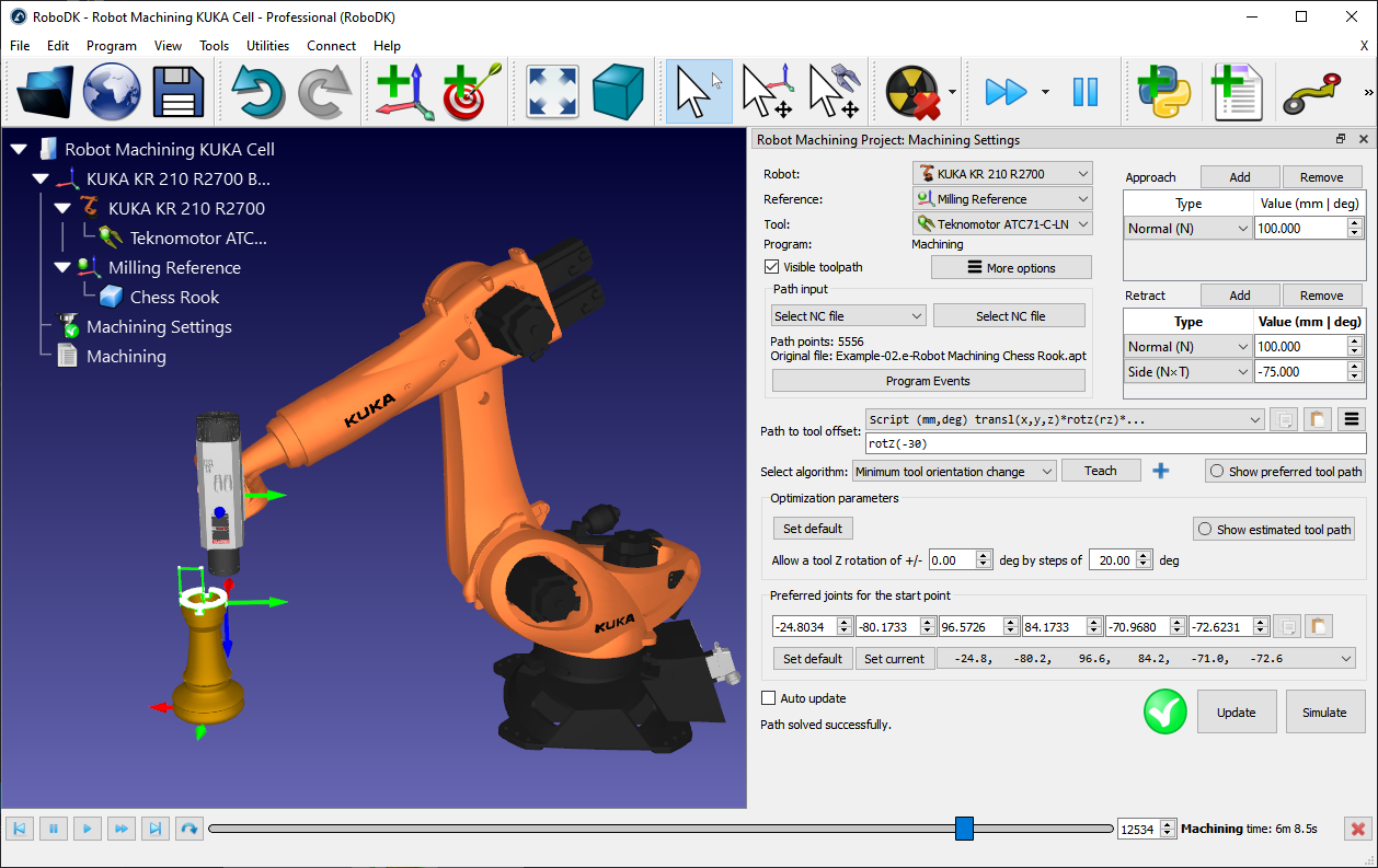
Update program
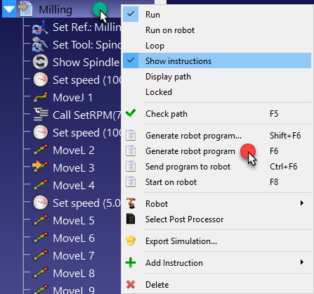
Select Update to generate the robot program given the provided settings. A green check mark is displayed if the program can be successfully created. You’ll then see a new program in the station called Machining.
Double click the generated 
Right click the program and select Generate robot program (F6) to generate the robot program. More information about program generation in the Program section.
Robot Cutting
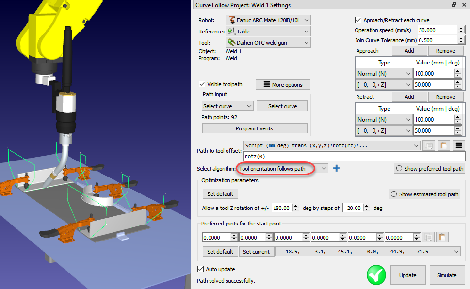
You can set the algorithm to keep the orientation of the tool constant along the path. This behavior may be useful for cutting or welding applications for example.
Select Tool orientation follows path in the Select algorithm dropdown to recalculate the preferred toolpath. The other settings are the same as having a Machining Project with a constant tool orientation.
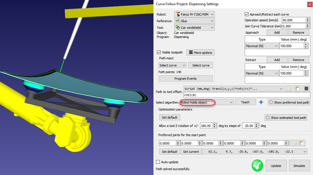
Robot Holds object
It is possible to program a robot when it holds the object/toolpath with the tool with the robot while the manufacturing operation takes place. This is useful for glue dispensing or polishing applications for example. This type of robot programming is also known as Remote TCP.
Select Robot holds object in the Select algorithm dropdown to properly place the toolpath on the TCP reference. The other settings are the same as having a Machining Project with a constant tool orientation.
More information available in the RoboDK Add-In for Autodesk Fusion section.
Curve Follow Project
You can make a robot follow curves in the 3D space using a Curve Follow Project (CFP). Curves in RoboDK can be selected from object edges or imported as a list of points in CSV files. A curve follow project is useful for some manufacturing operations such as robot welding, deburring, polishing, or painting for example.
To work with a CFP, Follow this procedure:
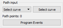
1.Click on Utilities➔Curve Follow Project to open the curve follow settings. These settings are the same as a Robot Machining Project, the only difference is that the Path input is preset to Select curve.
2.Click on the Select curve button to select the curve(s) on the screen.
3.Select the curves with a mouse left click. Selecting the same curve twice will swap the direction of motion. Also, right clicking a previously selected curve allows swapping the sense of motion, deselecting a previously selected curve or selecting an existing curve again.
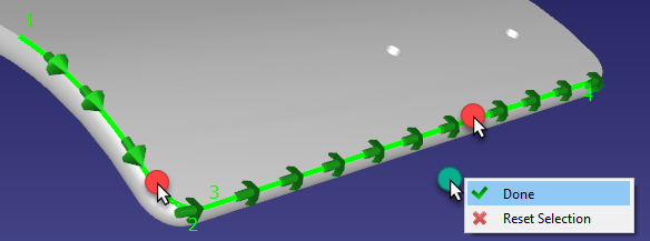
Right click on the 3D window and select Done or press the Esc key to go back to the settings menu. You can also double click on an empty space to go back to the settings menu. The green path will display the robot motion with respect to the object.
4.You can select Update to see if you can create a robot program with the default settings. If the program was generated successfully, you’ll see a green check mark. You can then select Simulate or double click the generated program to see the simulation start.
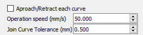
Additional options are available at the top right of the settings, such as the tool speed and if the approach/retract moves must be applied for each curve. The default settings are shown in the following image:
The program can be further customized and optimized using the same features as shown in the robot machining section.
Extract Features from 3D objects
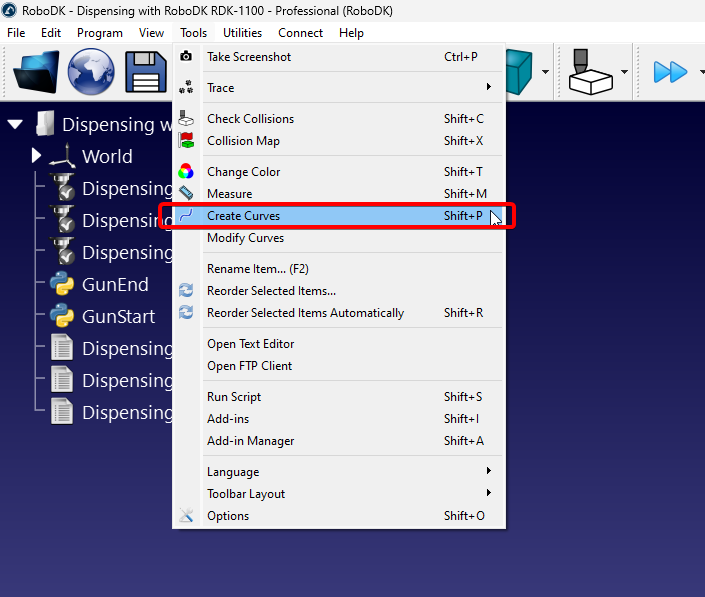
Curves can be extracted from the feature of 3D objects imported to RoboDK by selecting Tools➔Create Curves.
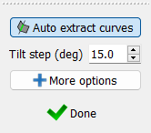
A panel will appear on the left side of the RoboDK Window, you will be able to extract curves as long as this panel is active and the “Auto extract curves” option is enabled.
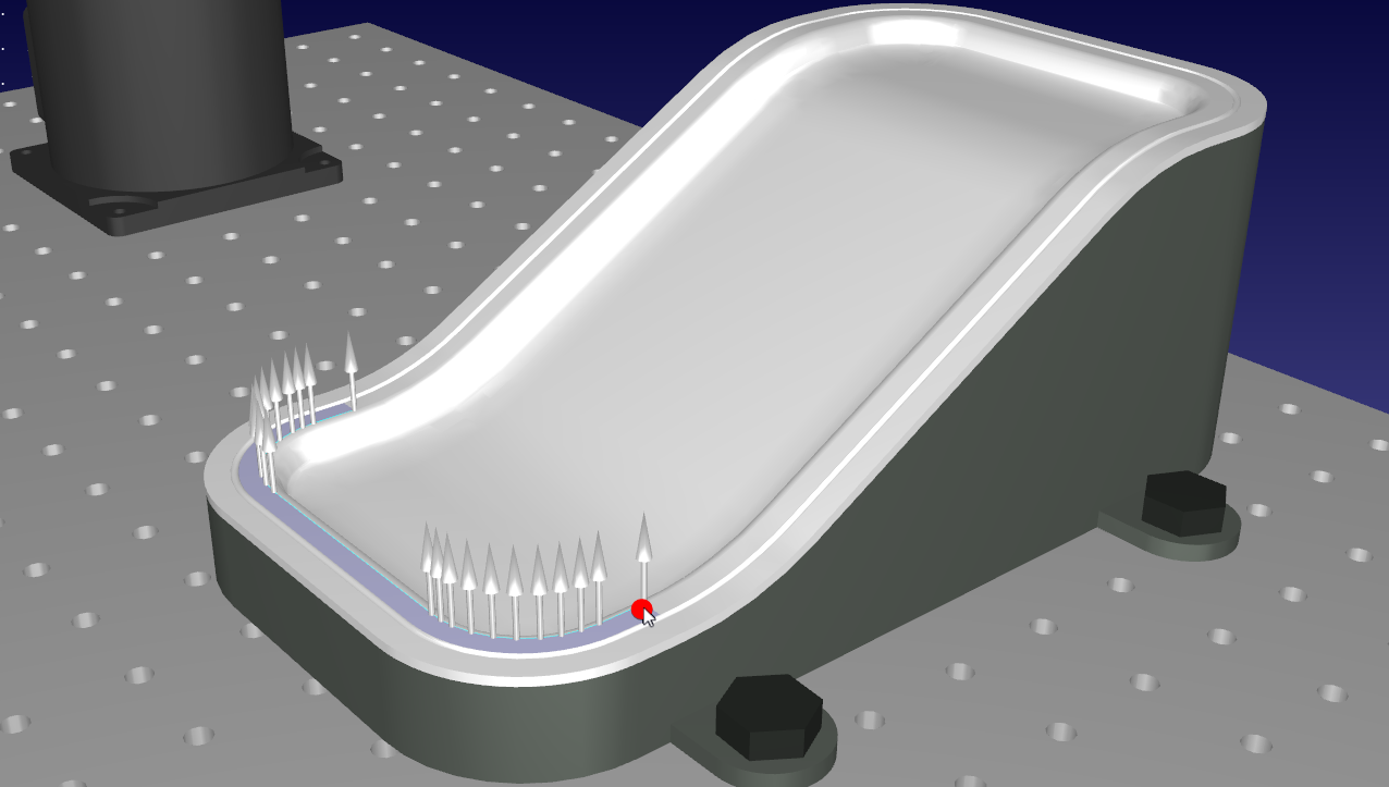
You can hover your cursor over the 3D object you want to extract the curve from. A thin and light blue line will appear to represent the curve. White arrows on different points represent the curve normal, this is the direction the tool will approach from.
You can change the orientation of the curve normals (approach direction) by lightly shifting the mouse vertically or horizontally. The default step size is 15 degrees and is controlled by the “Tilt step (deg)” option on the Create Curve Panel.
When you have identified the right curve, click on it without shifting your mouse. Repeat until you have selected all the curves you want to use on a Curve Follow Project.
RoboDK includes different tools to help you modify curves even after extracting them. If you simply want to modify the normal, you can do it by going to Tools➔Modify Curves. This feature will allow you to change the normals on any previously created curve.
Import Curves
RoboDK can create or obtain curves from a variety of sources. The following list shows examples of tools that will create a curve that can be used in a Curve Follow Project:
a.Extract features from a 3D Object imported into RoboDK.
b.Import a CSV File containing the curve.
c.Import a curve using a CAD/CAM Plugin.
d.Import curves from a SVG or DXF File.
e.Using the Surface Pattern Generator App
f.Using the RoboDK API to integrate with external applications.
g.Using a hand probe such as RoboDK TwinTrack
Import a CSV file
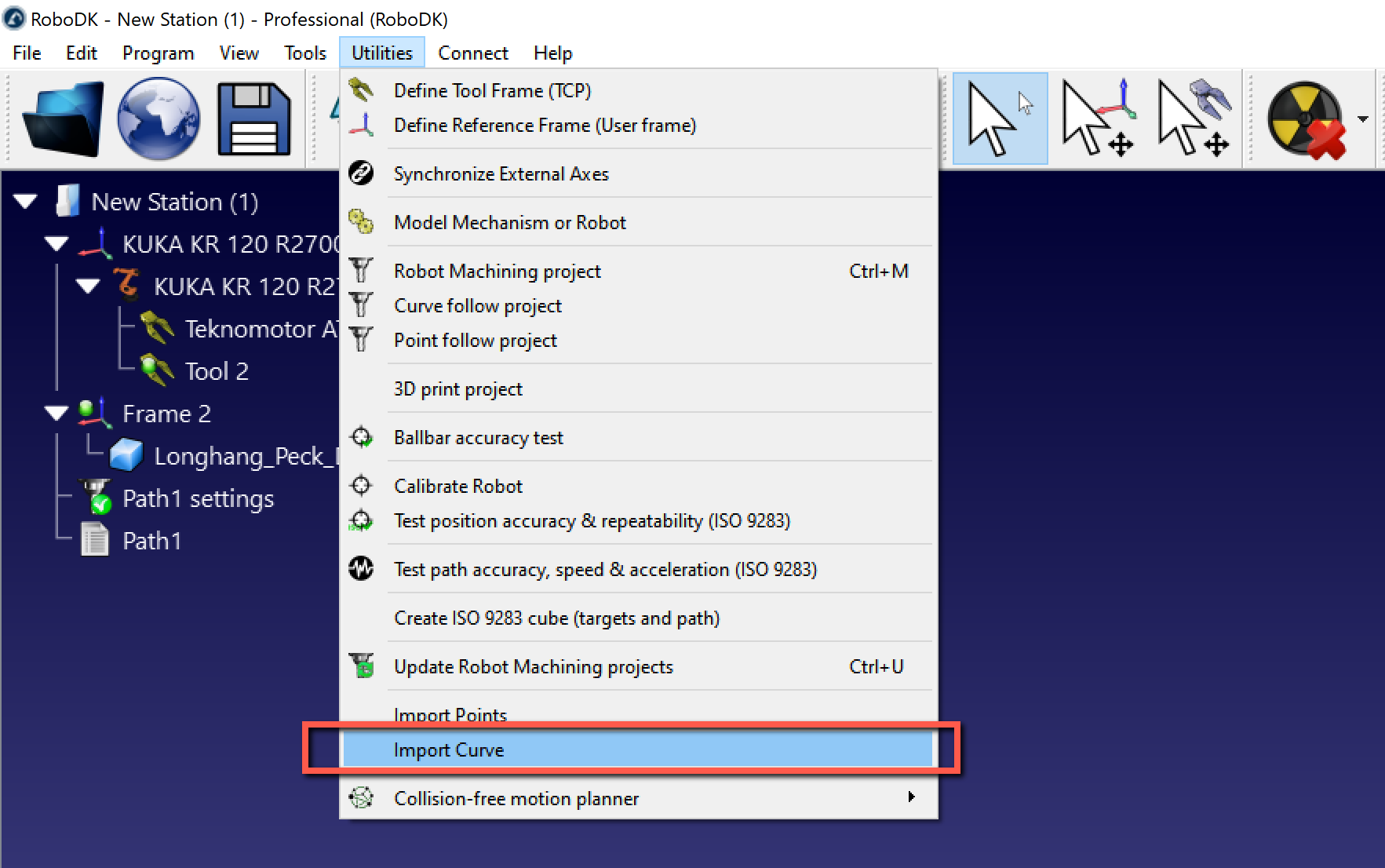
Curves can be imported in RoboDK from a CSV file or a text file by selecting Utilities➔Import Curve. A new item will appear in the station showing the curve as an object.
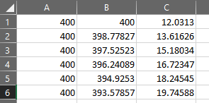
The file can be a text file with the 3D coordinates of each point of the curve. Optionally, the orientation of the Z axis of the tool can be provided as an i,j,k vector. All coordinates must be relative to the coordinate system of the part.
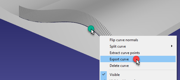
Optionally, existing curves of an object can be exported as a CSV file (right click a curve, then, select Export curve), modified and reimported back in RoboDK.
More information and examples on how to customize import of CSV or TXT files as curves or points is available in the examples section of the RoboDK API.
Point Follow Project
You can easily simulate a robot to follow points with RoboDK. Points in RoboDK can be extracted from objects, curves or imported as a list of points in CSV files. This option is useful for spot welding or drilling applications for example. The following video shows an example to set up a spot welding application: watch video.
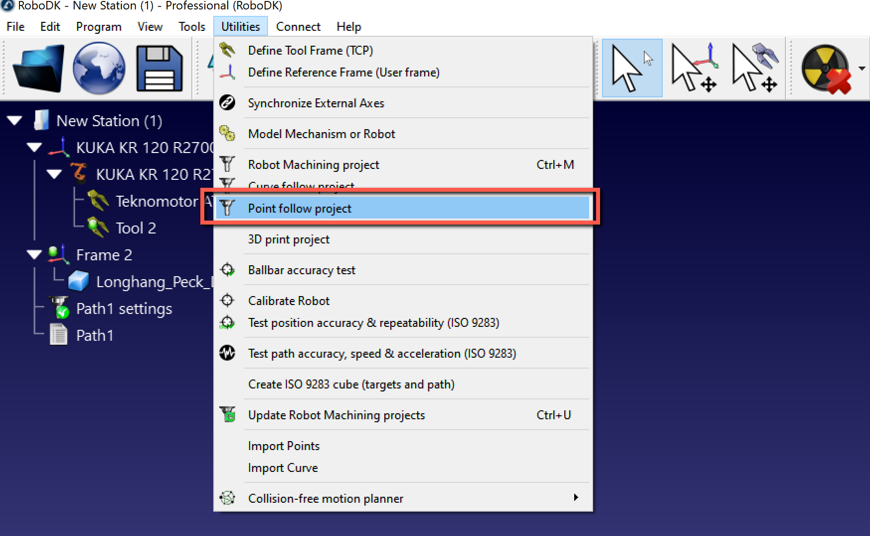
Select Utilities➔Point Follow Project to open the point follow settings. These settings are the same as a Robot Machining Project, the only difference is that the Path input is preset to Select points.
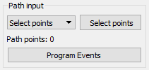
Select Select points to select the point(s) on the screen.
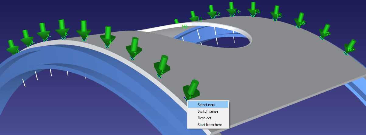
Select the points with a mouse left click. Selecting the same point twice will switch the approach direction. Also, right clicking a point allows selecting the points that follow by selecting Select next.
Right click the screen and select Done or press the Esc key to go back to the settings menu. The green path will display the robot motion with respect to the object.
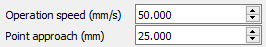
Some additional options are available at the top right of the settings, such as the tool speed and the approach distance. The default settings are shown in the next image:
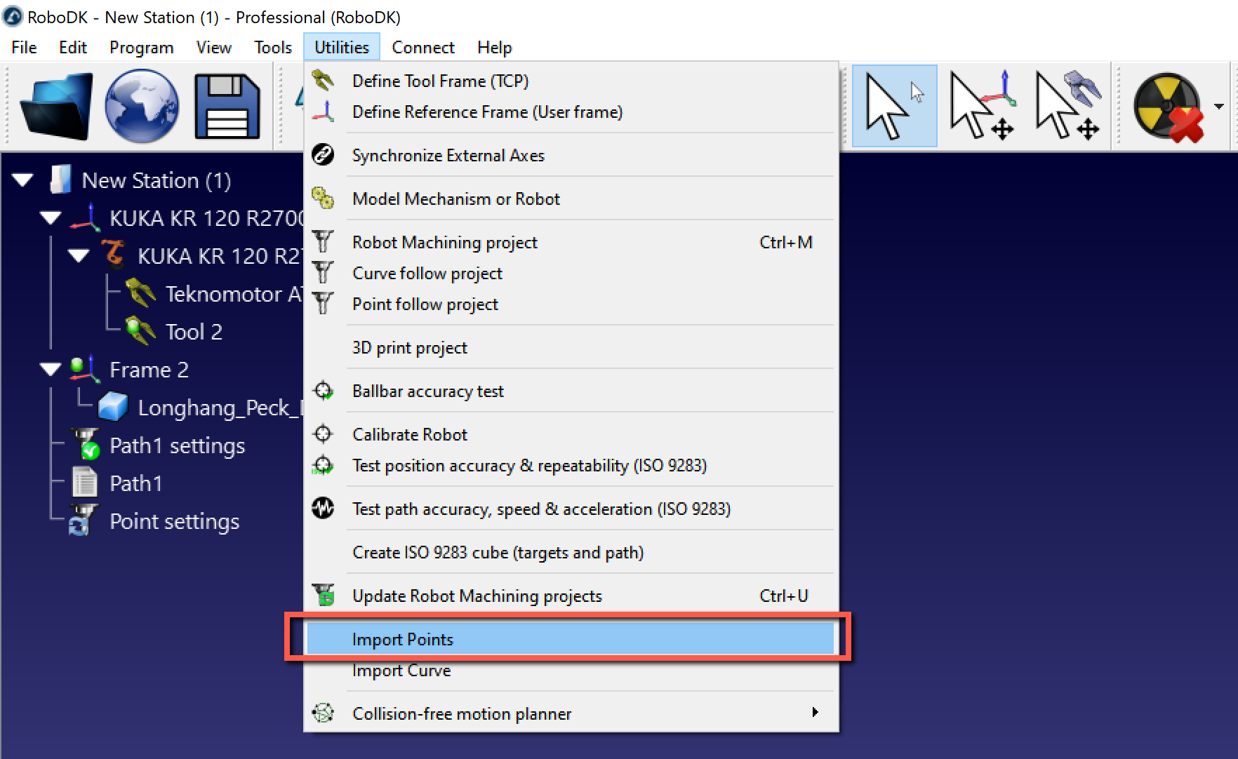
Import Points
A list of points can be imported from a text file or a CSV file by selecting Utilities➔Import Points. A new item will appear in the station showing the points as an object.
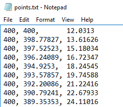
The file can be a text file with the 3D coordinates of each point of the curve. Optionally, the orientation of the Z axis of the tool can be provided as an i,j,k vector.
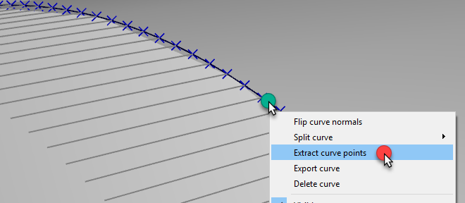
Optionally, existing curves of an object can be converted into points by right clicking a curve, then, selecting Extract curve points.
Robot 3D Printing Project
Additive manufacturing (or 3D printing) is the process of making three dimensional solid objects from a digital file. Industrial robot arms can be used as a 3-axis or a 5-axis 3D printer with RoboDK. The following video shows an overview of how to setup 3D printing with RoboDK offline: watch video.
3D printing with robots is possible in one of the following ways:
●Directly convert G-code programs (NC file) to robot programs with RoboDK, as shown with the Robot Machining project. The rate of material flow (extruder directive E) is properly calculated for each movement and it can be integrated in the generated program as a Program Event. G-code is a type of NC file supported by RoboDK and it is also a format supported by many 3D printers. Most slicer software can generate G-code given an STL file.
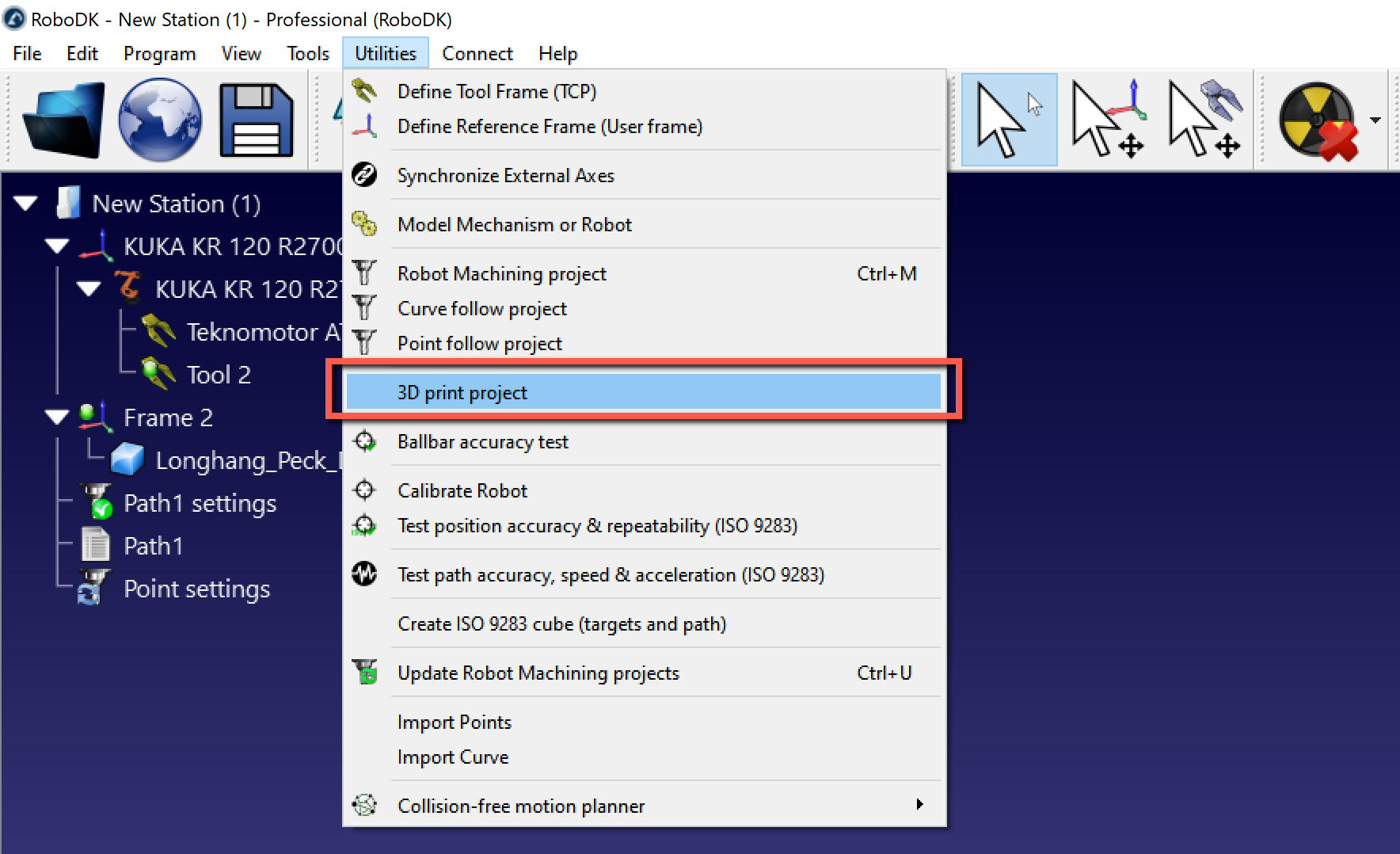
●Select Utilities➔3D Print Project to open the 3D printing settings.
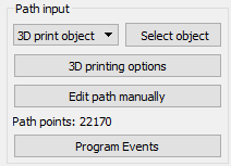
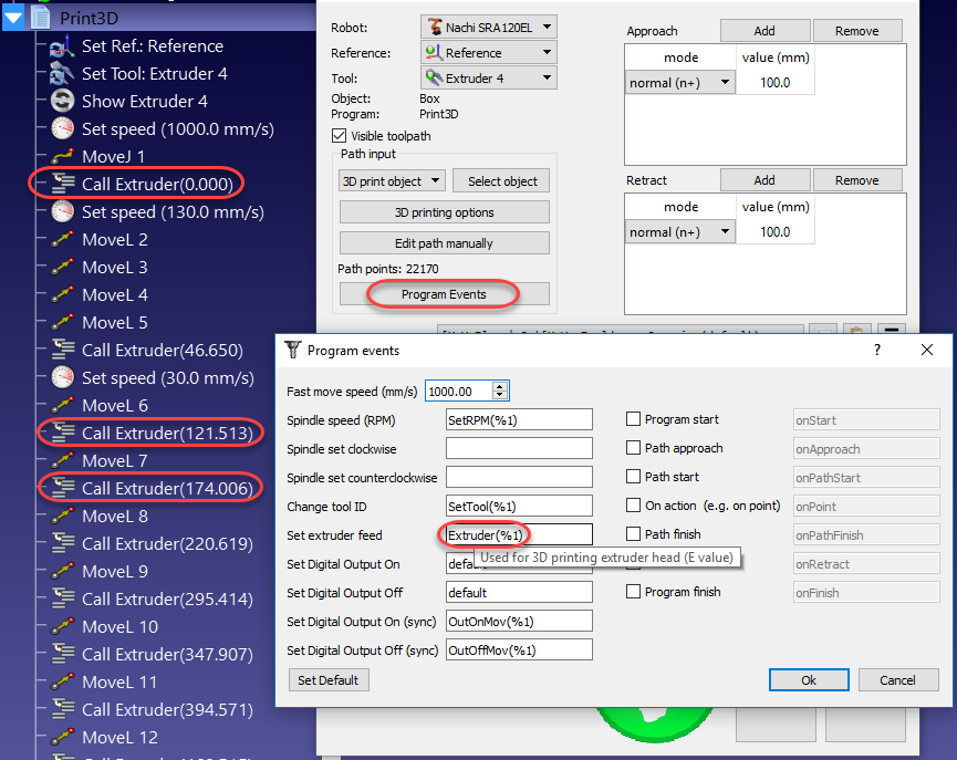
By default, RoboDK translates the E directive as a program call to a program called Extruder and passing the E value as a parameter. Select Program Events to change this behavior.
The Extruder value (E) represents how much material needs to be extruded before each movement. This value can be used to drive the extruder feed from the robot taking into account the robot speed and distance between points.
Alternatively, it is possible to calculate the extruder feed using a post processor and generate appropriate code accordingly. The following section provides an example.
Post Processor for robot 3D printing
This section shows how to modify a robot post processor to calculate the extruder speed before executing a movement instruction for 3D printing. Alternatively, these operations can be made on the robot controller with the Extruder program call (default command to drive the extruder).
By customizing a robot post processor, it is possible to make the integration of an extruder for 3D printing easier before sending the program to the robot. To accomplish such task, we need to do some calculations and output customized code when the program is generated in the robot post processor.
The first step is to intercept the Extruder calls and read the new Extruder values (E values) inside the RunCode section in the post processor. The following section processes all program calls generated for a program:
def RunCode(self, code, is_function_call = False):
if is_function_call:
if code.startswith("Extruder("):
# Intercept the extruder command.
# if the program call is Extruder(123.56)
# we extract the number as a string
# and convert it to a number
self.PRINT_E_NEW = float(code[9:-1])
# Skip the program call generation
return
else:
self.addline(code + "()")
else:
# Output program code
self.addline(code)
The Extruder value (length/E) is saved as the PRINT_E_NEW variable in the robot post processor.
We need to trigger a function call named new_move with each new linear movement instruction. We can add this call at the beginning of the MoveL command:
def MoveL(self, pose, joints, conf_RLF=None):
"""Add a linear movement"""
# Handle 3D printing Extruder integration
self.new_move(pose)
...
We must also add the following variables in the header of the post processor to calculate the extruder increments:
# 3D Printing Extruder Setup Parameters:
PRINT_E_AO = 5 # Analog Output ID to command the extruder flow
PRINT_SPEED_2_SIGNAL = 0.10 # Ratio to convert the speed/flow to an analog output signal
PRINT_FLOW_MAX_SIGNAL = 24 # Maximum signal to provide to the Extruder
PRINT_ACCEL_MMSS = -1 # Acceleration, -1 assumes constant speed if we use rounding/blending
# Internal 3D Printing Parameters
PRINT_POSE_LAST = None # Last pose printed
PRINT_E_LAST = 0 # Last Extruder length
PRINT_E_NEW = None # New Extruder Length
PRINT_LAST_SIGNAL = None # Last extruder signal
Finally, we need to define a new procedure that will generate appropriate extruder feed commands according to the distance between movements, the robot speed and the robot acceleration. This assumes the extruder feed is driven by a specific analog output or a customized program call.
We need to add the following code before the def MoveL program definition.
def calculate_time(self, distance, Vmax, Amax=-1):
"""Calculate the time to move a distance with Amax acceleration and Vmax speed"""
if Amax < 0:
# Assume constant speed (appropriate smoothing/rounding parameter must be set)
Ttot = distance/Vmax
else:
# Assume we accelerate and decelerate
tacc = Vmax/Amax;
Xacc = 0.5*Amax*tacc*tacc;
if distance <= 2*Xacc:
# Vmax is not reached
tacc = sqrt(distance/Amax)
Ttot = tacc*2
else:
# Vmax is reached
Xvmax = distance - 2*Xacc
Tvmax = Xvmax/Vmax
Ttot = 2*tacc + Tvmax
return Ttot
def new_move(self, new_pose):
"""Implement the action on the extruder for 3D printing, if applicable"""
if self.PRINT_E_NEW isNone or new_pose is None:
return
# Skip the first move and remember the pose
if self.PRINT_POSE_LAST isNone:
self.PRINT_POSE_LAST = new_pose
return
# Calculate the increase of material for the next movement
add_material = self.PRINT_E_NEW - self.PRINT_E_LAST
self.PRINT_E_LAST = self.PRINT_E_NEW
# Calculate the robot speed and Extruder signal
extruder_signal = 0
if add_material > 0:
distance_mm = norm(subs3(self.PRINT_POSE_LAST.Pos(), new_pose.Pos()))
# Calculate movement time in seconds
time_s = self.calculate_time(distance_mm, self.SPEED_MMS, self.PRINT_ACCEL_MMSS)
# Avoid division by 0
if time_s > 0:
# This may look redundant but it allows you to account for accelerations and we can apply small speed adjustments
speed_mms = distance_mm / time_s
# Calculate the extruder speed in RPM*Ratio (PRINT_SPEED_2_SIGNAL)
extruder_signal = speed_mms * self.PRINT_SPEED_2_SIGNAL
# Make sure the signal is within the accepted values
extruder_signal = max(0,min(self.PRINT_FLOW_MAX_SIGNAL, extruder_signal))
# Update the extruder speed when required
if self.PRINT_LAST_SIGNAL isNone or abs(extruder_signal - self.PRINT_LAST_SIGNAL) > 1e-6:
self.PRINT_LAST_SIGNAL = extruder_signal
# Use the built-in setDO function to set an analog output
self.setDO(self.PRINT_E_AO, "%.3f" % extruder_signal)
# Alternatively, provoke a program call and handle the integration with the robot controller
#self.addline('ExtruderSpeed(%.3f)' % extruder_signal)
# Remember the last pose
self.PRINT_POSE_LAST = new_pose
Robot 3D Printing with Cura
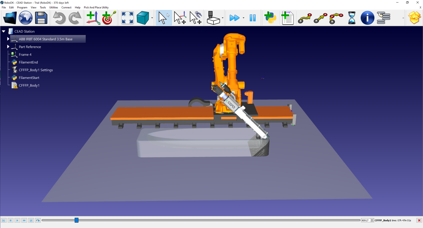
Additive manufacturing (or 3D printing) with robots can be accomplished by preparing toolpaths in a slicer such as Ultimaker Cura and converting the generated G-code into robot programs with RoboDK.
This example demonstrates how to use Cura with RoboDK for large-scale 3D printing of a boat hull mould using an ABB IRB 6640 robot, a CEAD extruder, and an ABB IRBT 6004 linear rail.
3D printing with Cura and RoboDK is possible in one of the following ways:
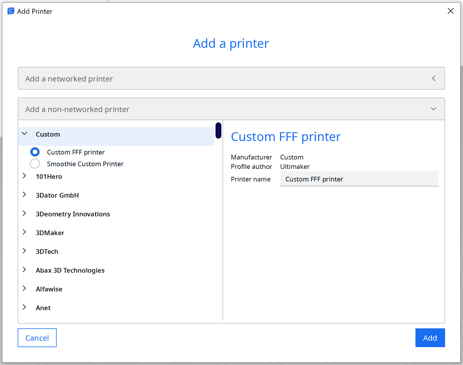
1.Create a Custom FFF Printer in Cura to match the robot’s workspace.
2.Import the 3D model (STL file) into Cura and apply a 45° tilt before slicing.
3.Slice the rotated STL and generate a G-code program.
4.Convert the Cura G-code to a robot program in RoboDK.
5.Simulate the tilted extrusion process in RoboDK and export ABB RAPID code.
Create a Custom Printer in Cura
Open Ultimaker Cura → Settings → Printer → Add Printer, then select Custom → Custom FFF Printer.
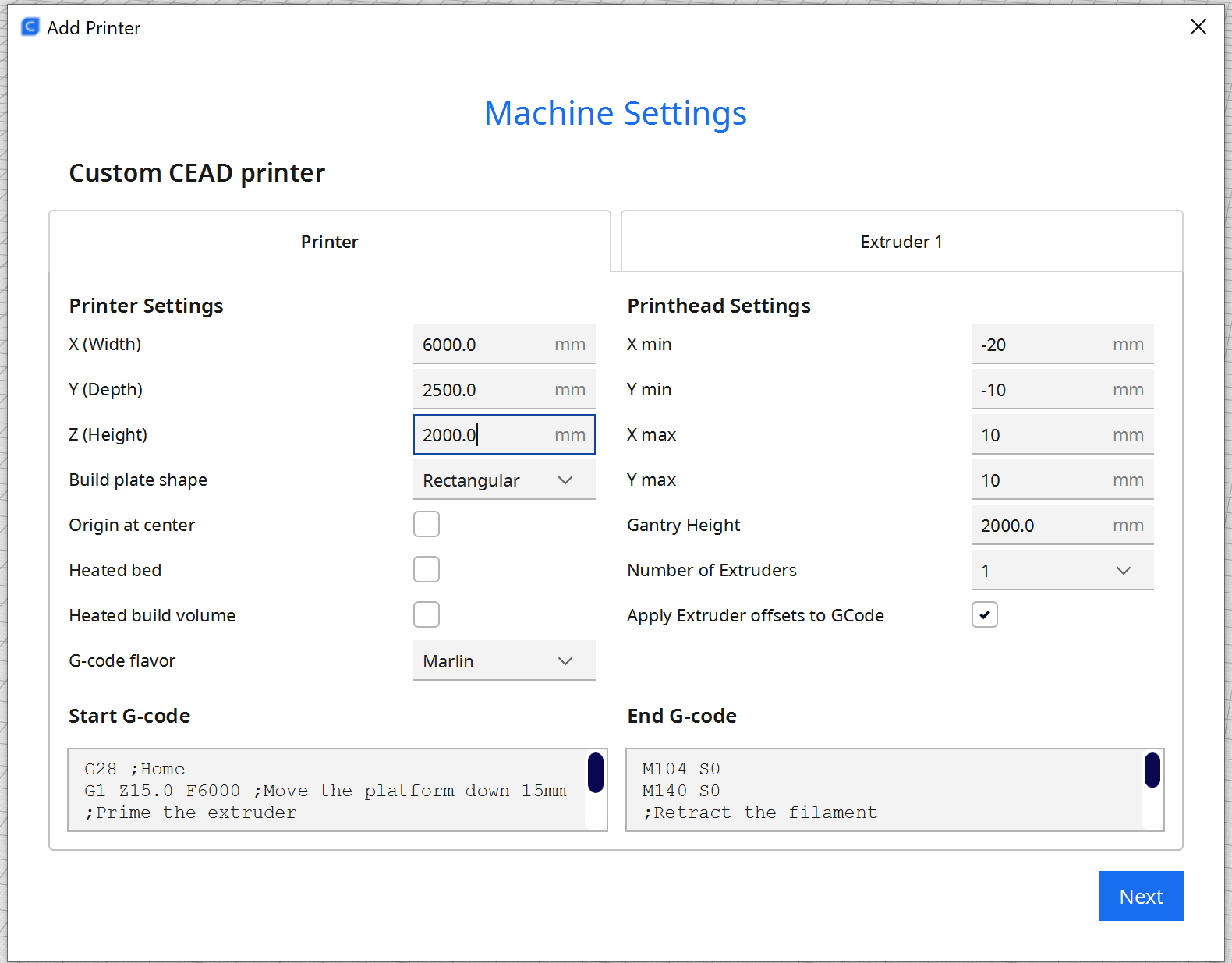
Set the build volume to match the robot and rail:
1.X: 6000 mm
2.Y: 2500 mm
3.Z: 2000 mm
Disable heater controls because the CEAD extruder manages heating externally.
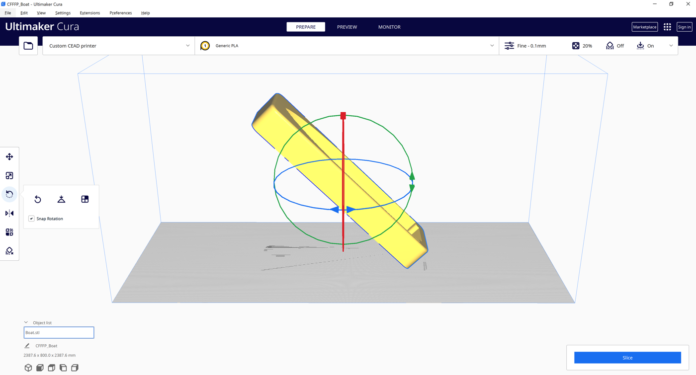
Apply a 45° Tilt in Cura
The STL model must be rotated 45° in Cura before slicing.
1.Select the object.
2.Use Cura’s Rotate tool to tilt the part 45°.
3.Slice the rotated STL.
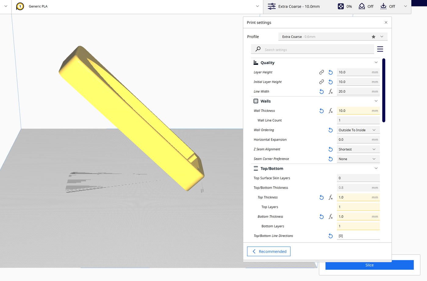
Generate and Import G-code
After tilting the model, slice it in Cura and save the program as a .gcode file.
In RoboDK, select Utilities → Convert NC Program and choose the Cura file.

In the NC import dialog:
1.Select the ABB IRB 6640 robot.
2.Add the ABB IRBT 6004 rail as an external axis.
3.Select the CEAD extruder as the tool.
4.Define the reference frame (boat hull platform).
Extruder Synchronization
By default, RoboDK translates Cura’s E directive as a program call to a program called Extruder, passing the E value as a parameter.
This can be modified in Tools → Options → Program Events.

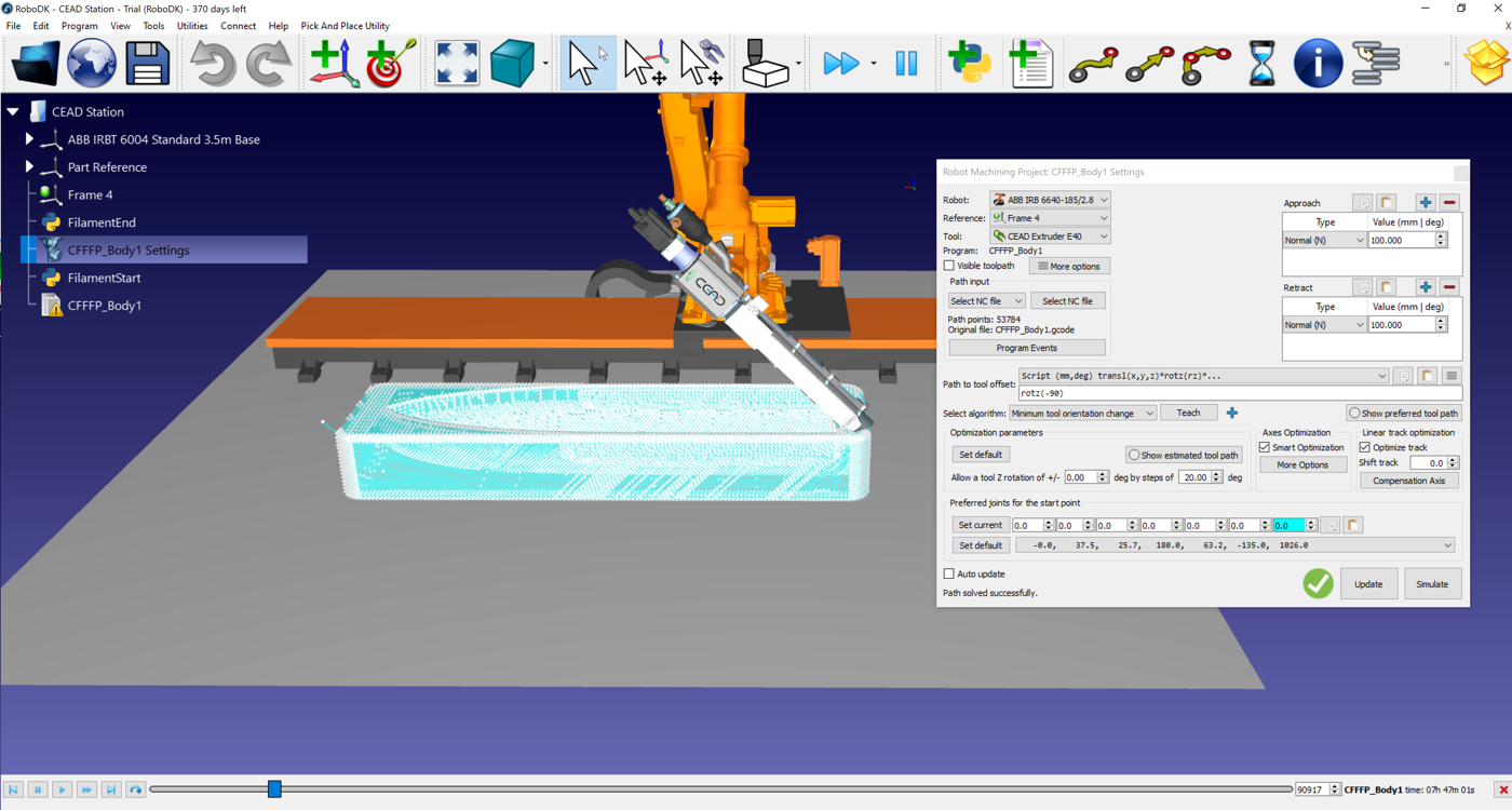
Simulation of 45° Printing
When the Cura G-code is imported, RoboDK simulates the tilted extrusion process:
1.The ABB IRB 6640 follows the Cura toolpath.
2.The CEAD extruder is synchronized with robot motion.
3.The tool orientation reflects the 45° tilt applied in Cura.