Robot Programs
RoboDK is a simulator focused on industrial robot applications. This means that robot programs can be created, simulated and generated offline for a specific robot arm and robot controller. In other words, RoboDK is software for Offline Programming.
To create robot programs, it is required to select a robot, load the robot tools and use one or more CAD to path features to create programs by adding targets or using specific tools (such as converting CNC programs to robot programs).
An extensive library of industrial robots is available. Industrial robots are modelled in RoboDK the same way they behave using vendor-specific controllers, including axis limits, sense of motion and axis linking.
This section shows how robot programs can be created, simulated and generated for a specific robot controller using the RoboDK Graphical User Interface (GUI).
Offline Programming
Offline Programming (or Off-Line Programming) means programming robots outside the production environment. Offline Programming eliminates production downtime caused by shop floor programming (programming using the teach pendant).
Simulation and Offline Programming allows studying multiple scenarios of a robot cell before setting up the production cell. Mistakes commonly made in designing a work cell can be predicted in time.
Offline Programming is the best way to maximize return on investment for robot systems and it requires appropriate simulation tools. The time for the adoption of new programs can be cut from weeks to a single day, enabling the robotization of short-run production.
Create a Program
A simulation can be accomplished by adding a sequence of instructions in a program. Each instruction represents specific code for a specific controller, however, RoboDK offers a Graphical User Interface (GUI) to easily build robot programs, in a generic way, without the need to write code.
The code specific to a robot controller will be generated automatically when the program is generated. To create a new empty program using the RoboDK Graphical User Interface:
1.Select Program➔
Alternatively, select the corresponding button in the toolbar.
2.Select Tools➔Rename item… (F2) to rename the program
This action will create an empty program and will allow adding new instructions by right clicking the program or selecting an instruction from the Program menu. The next section Program Instructions provides more information about adding instructions.
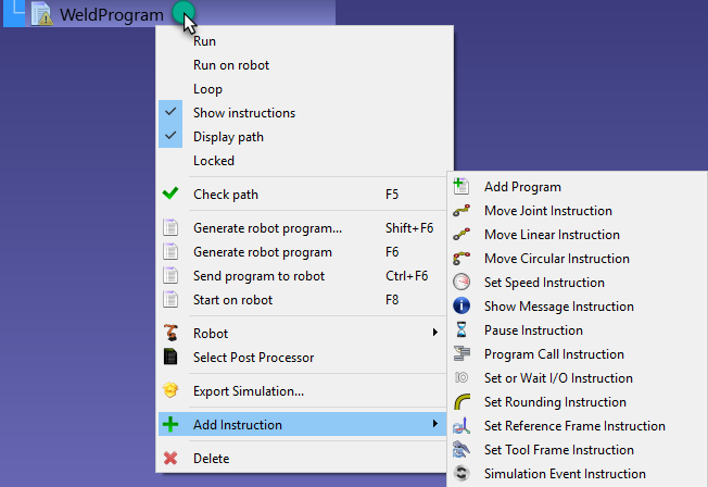
Program Instructions
It is possible to add new instructions by right clicking a program or from the Program menu, as shown in the previous section.
This section describes the instructions supported by the RoboDK graphical user interface for robot offline programming.
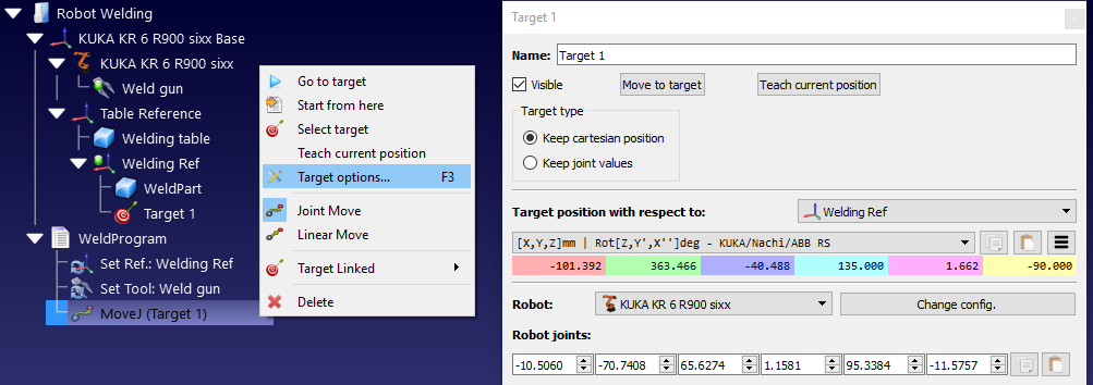
Joint Move
Select Program➔
Unless a target is selected before adding the instruction, the movement instruction will create a new target and they will be linked. If the target is moved the movement is also modified.
If this is the first instruction that is added to the program, two more instructions will be added before the movement instruction: a Reference Frame selection and a Tool Frame selection. This will make sure that when the program reaches the movement instruction the robot is using the same reference and tool frames used to create this new target.
Linear Move
Select Program➔
Unless a target is selected before adding the instruction, the movement instruction will create a new target and they will be linked. If the target is moved the movement is also modified.
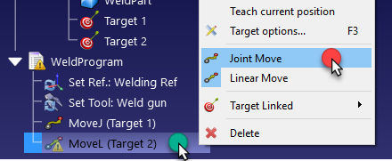
Joint Moves and Linear Moves behave the same way and can be easily switched from one type to the other.
Same as with the Joint Move Instruction, if this is the first instruction that is added to a program, two more instructions will be added before the movement instruction: a Reference Frame selection and a Tool Frame selection.
Contrary to Joint Movements, Linear Movements are sensitive to robot singularities and axis limits. For example, most robot arms can’t cross a singularity while performing a linear movement. The following image shows an example saying Joint 5 is too close to a singularity (0 degrees). Consider a Joint move instead.
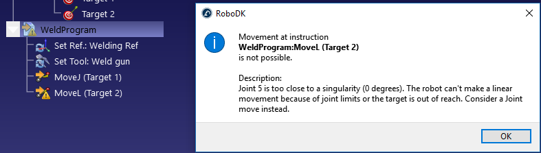
If a linear move is not strictly necessary, right-click the movement instruction and change it to a Joint Move Instruction.
Alternatively, the target, the TCP or the position of the reference frame must be modified to avoid the singularity.
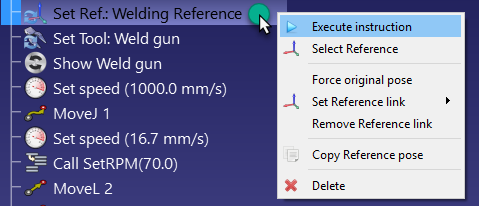
Set Reference Frame
Select Program➔ 
The reference frame is a variable also known as Work Object (ABB robots), UFRAME (Fanuc robots), FRAME (for Motoman robots) or $BASE (for KUKA robots).
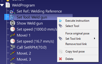
Set Tool Frame
Select Program➔ 
The reference frame is a variable also known as ToolData (ABB robots), UTOOL (Fanuc robots), TOOL (for Motoman robots) or $TOOL (for KUKA robots).
Circular Move
Select Program➔
Unless two targets are selected before adding the instruction, the movement instruction will create no new targets. It is required to add two more targets separately and link them from the circular move instruction, as shown in the next image.
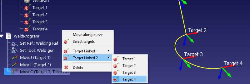
The circular path is an arc created from the point where the robot is located, passing through the first circular point (Target Linked 1) and ending at the end point (Target Linked 2).
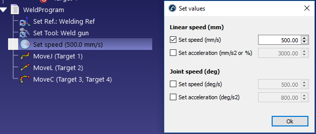
Set Speed
Select Program➔
Activate the corresponding cases to impose a specific speed and/or acceleration in the program. The robot speed is applied from the moment this instruction is executed.
The robot speed can also be changed in the robot parameters menu: Double click the robot, then, select parameters.
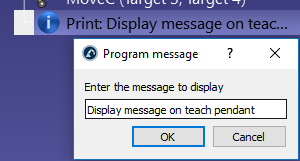
Show Message
Select Program➔
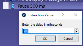
Pause
Select Program➔
Program call
Select Program➔
By default, this is a blocking call to a specific program. However, it is possible to switch to Insert Code to enter code specific at the location of this instruction. This might be useful for a specific application and a specific controller.
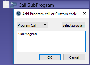
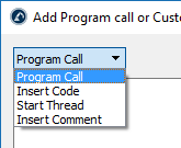
Switch from Program Call to Start Thread to provoke a non-blocking call to a sub program. In this case, the controller will start a new thread. This option is only available for certain controllers and only works for specific operations.
Set/Wait IO
Select Program➔
The IO Name can be a number or a text value if it is a named variable. The IO Value can be a number (0 for False and 1 for True) or a text value if it is a named state.
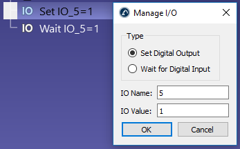
Set to Wait for Digital Input to stop the program execution until a specific input changes to a specific value. Furthermore, most robot controllers support a timeout delay to raise an error if the waiting time exceeds a specific value. Check the Timeout (ms) option to activate this feature.
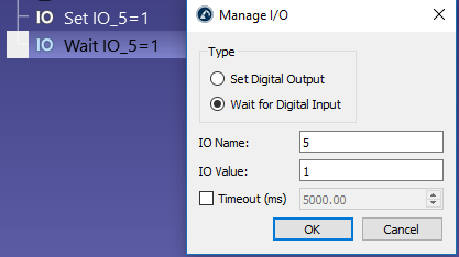
Altering simulated Digital Inputs and Digital Outputs will create new station variables. To check the state of these variables you can right click the station and select Station Parameters. It is also possible to read or modify these variables through the API.
Set Rounding value
Select Program➔
Without a rounding instruction, the robot will reach the speed of 0 at the end of each movement (unless the next movement is tangent with the previous movement). This will provoke high accelerations and quick speed changes to ensure the best accuracy for each movement.
This value is also known as Blending radius (Universal Robots), ZoneData (ABB robots), CNT/FINE (Fanuc robots), Cornering (Mecademic robots) or $APO.CDIS/$APO.CPTP/Advance (KUKA robots).
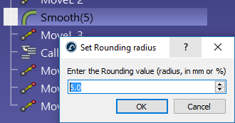
Some controllers require setting this value as a percentage, for example on a Fanuc controller, if you want to provide the command CNT5 you should enter the value 5.
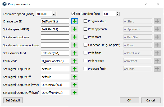
You can also specify the rounding parameter in the Program Events window if you are generating your programs for robot machining, 3D printing or curve/point following.
Simulation event
You can create specific events meant for simulation by using a simulation event instruction. Simulation events have no impact on the real robot or the generated robot program.
Select Program➔Simulation Event Instruction to add a custom simulation event. This type of instruction will provoke a specific event only for simulation purposes, such as attaching one object to a gripper, dropping it to a table or creating objects to simulate a feeder.
You can use the user interface to trigger the actions as simulation events:
1.Attach an object to a tool.
2.Detach an object from a tool and drop it to a coordinate system.
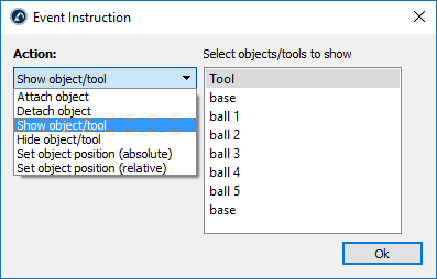
3.Show one or more objects or tools.
4.Hide one or more objects or tools.
5.Set the absolute position of one or more objects or reference frames.
6.Set the relative position of one or more objects or reference frames.
7.Set the robot joints to home.
8.Move conveyor.
9.Create object.
10.Delete objects.
11.Wait for object.

By combining the right simulation events you can create simulations with the user interface for material handling or move objects through conveyors in the simulation as desired.
Attach object
The attach object simulation event allows you to attach one object to a tool to simulate a pick action.
When the action to attach an object to a tool is triggered, the closest object to the selected tool will be attached. A default tolerance of 200 mm is used to ignore any objects farther than this distance.
If you don’t specify a distance tolerance, the global default value will be used (you can change the global default in Tools➔Options➔Maximum distance to attach an object to a robot tool). Also, by default, the distance is checked from the TCP location to the object reference. Alternatively, it is possible to use the distance between the TCP and the object geometry by selecting Check shortest distance between TCP and the object shape.
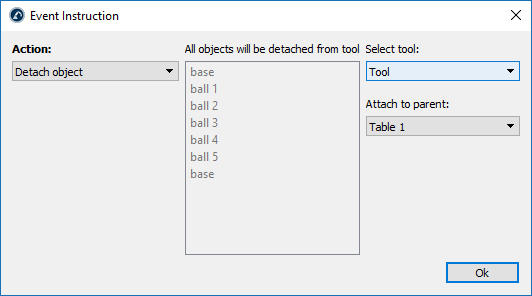
Detach object
The detach object simulation event allows you to detach an object from a tool to another object or coordinate system.
You should choose the tool where the objects should be detached from and the coordinate system or object where the objects should be attached to afterwards.
The detach object simulation event allows you to simulate a place/drop operation in a plick and place application (performing the opposite action of the attach event).
For example, if the robot moves to a specific location to grab an object, we can set up an Attach object event to move that object together with the robot. Then, after the robot has moved and it is ready to drop the grabbed objects, you can trigger a Detach object event to leave any objects the robot tool has grabbed.

Show objects or tools
The show objects or tools event allows you to make one or more objects, tools or robots visible within the simulation environment.
You can select one or more items by holding the Ctrl key.
Hide objects or tools
The Hide objects or tools event allows you to make one or more objects or tools invisible within the simulation.
You can select one or more items by holding the Ctrl key.

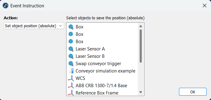
Set the absolute position
The Set object position (absolute) allows you to update the position of every object you selected when this action is triggered. The parent reference that each item is attached to is not modified. Only the position of each object is updated.
You can select one or more items by holding the Ctrl key. The current position of the item is recorded when you press OK.
Set the relative position
The Set object position (relative) allows you to update the position and parent of every object you selected when this action is triggered. The parent reference that each item is attached to is also modified and the position of each object is also updated.
You can select one or more items by holding the Ctrl key. The current position of the item and the parent item it is attached to is recorded when you press OK.
The difference between this instruction and the absolute position instruction is that this instruction also updates the parent item that each object is attached to.
Set the robot to home
The set joints to home event triggers the selected robot or mechanisms to move to its defined "home" joint positions immediately (the movement is not simulated over time).
This is useful when you need to reset a simulation and place the conveyors at the start position.
You can select one or more items by holding the Ctrl key.
Move conveyor event
The move conveyor event simulates moving the conveyor by a specific distance, simulating the effect of the movement over time.
This is useful when you need to simulate a specific increment for processing an object on the conveyor once it moves a specific distance.
Create object
The Create object instruction allows you to simulate a feeder by creating a new object in the simulation environment.
You should select the model object to create and the parent reference where the items should be attached to.
This action is useful to create new objects in a conveyor.
Delete objects
The Delete objects instruction removes objects from the simulation environment.
You should select a model object that you would like to delete. Any object that matches the name and geometry of the same object is deleted when this action is triggered. The model object selected and any locked objects are not removed.
This instruction helps clean up a simulation that has finished and you have many objects that were created by the Create object instruction.

Wait for object
The Wait for object instruction waits for an object to be in contact with another object to trigger a specific action.
This event is useful when you want to trigger. It is common to place this instruction by itself in a program running in a loop that performs a specific action when an object is in contact with a sensor.

The actions you can perform when an object is in contact with the sensor are the following:
1.Stop a robot: you should select the robot or mechanism that should stop.
2.Delete an object: the object should be removed from the station.
3.Wait for the object only (for example, you can trigger a robot to pick an object).
4.Move an object to another coordinate system. For example, to attach an object from one conveyor to another.

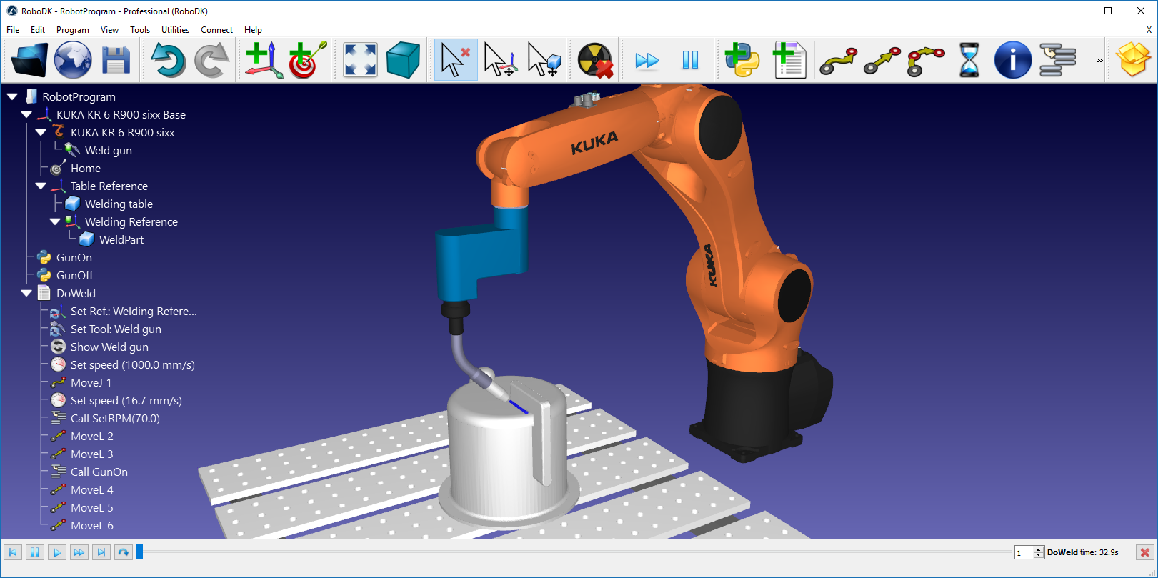
Simulate Program
To start the simulation of a program you can simply double click on the program item.
Alternatively, you can also:
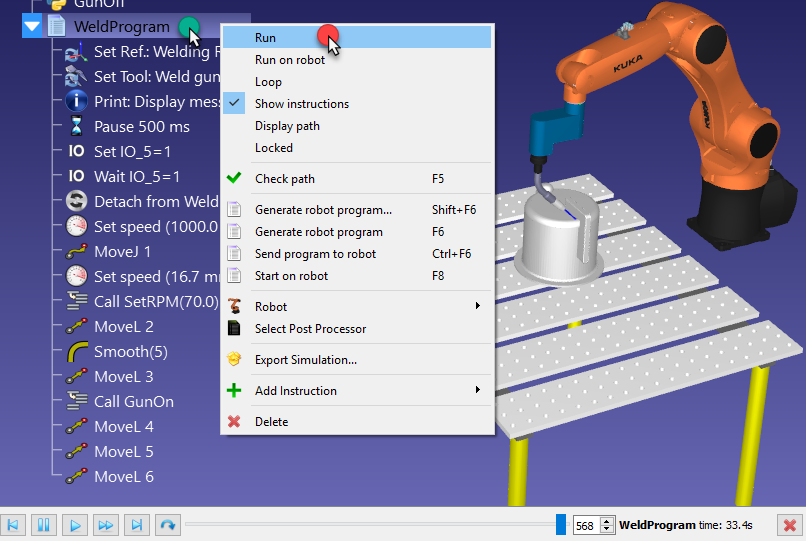
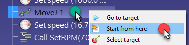
1.Right click the program
2.Select Run
A simulation bar will appear at the bottom if the program is double clicked. It is possible to slide the simulation to move the simulation forward or backwards using the simulation bar.

RoboDK simulates 5 times faster than real time by default. That means that if a program takes 30 seconds to execute it will be simulated in 30/5=6 seconds. Speeding up the simulation increases this ratio to 100. Normal and fast simulation speeds can be changed in the Tools➔Options➔Motion menu.


Generate Program
When you have a program ready to be exported to the robot you can generate the program file required by your robot controller.
Follow these steps to generate a robot program:
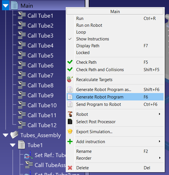
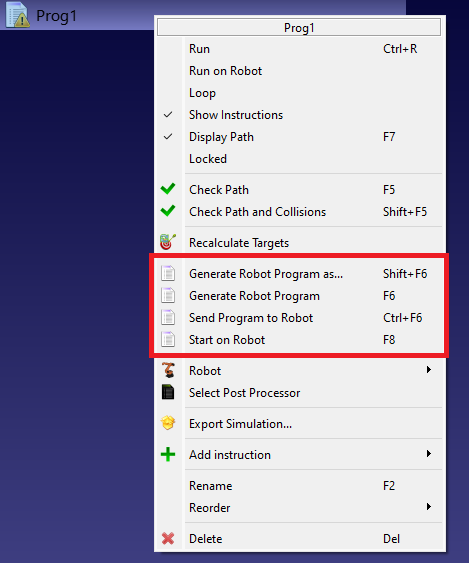
1.Right click a program.
2.Select Generate Robot Program (F6).
You should then see the robot program displayed in a text editor.

Robot programs are saved in the Documents folder by default (C:/Users/Your Name/Documents/RoboDK/Programs/). You can change this folder by selecting Tools➔Options, select the Program tab and click on Set right beside the Robot programs folder.
Alternatively, you can also right click a program and select Generate Robot Program as … (Shift+F6) to generate the program specifying the location where you would like to save it.
Transfer Program
It is possible to transfer a program from the computer directly to the robot. This option usually sends the program to the robot through FTP protocol or other specific protocols, such as using socket messaging or serial connection. First, it is required to enter the robot IP and FTP settings in the robot connection menu:
1.Right click a robot.
2.Select Connect to robot… A window will appear on the left.
3.Enter the robot IP.
4.Select More options to enter the FTP settings and FTP credentials (if required)

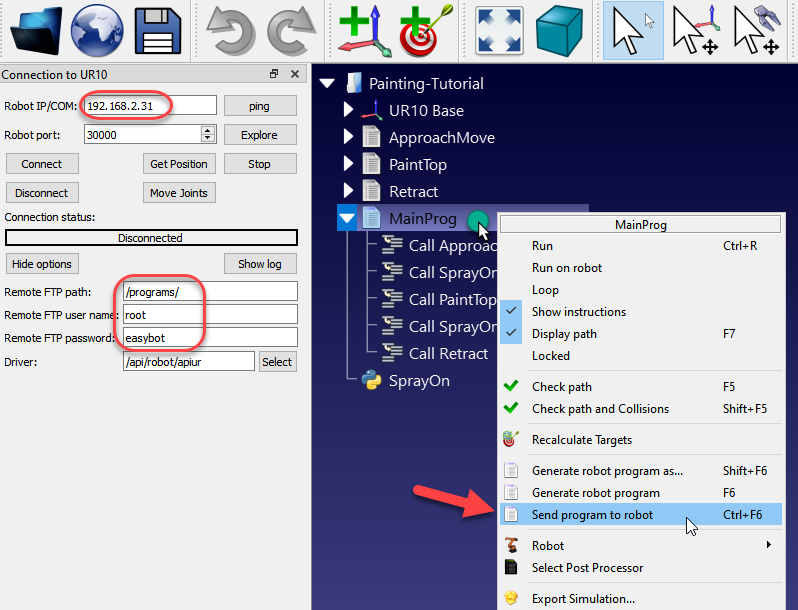
Once the network settings have been provided and the robot is properly connected, follow these steps to transfer the program to the robot directly from RoboDK:
1.Right click a program.
2.Select Send program to robot (Ctrl+F6).
A popup window will display the status (success or failed).
Select Post Processor
The conversion from the RoboDK simulation to a specific robot program is done by a Post Processor. The Post Processor defines how robot programs should be generated for a specific robot. Each robot has a specific/default post processor by default in RoboDK.
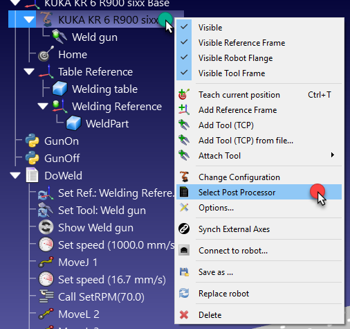
To select a specific post processor for a robot:
1.Right click a robot or a program.
2.Select Select Post Processor.
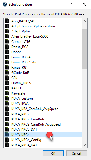
3.Choose a post processor from the list.
4.Select OK.

The change is now applied, and you can program can be generated again to see the result.
Post Processors in RoboDK provide complete flexibility to generate the robot programs for specific requirements. RoboDK provides Post Processors for most robot brands. Post processors can be easily created or modified. More information about post processors in a dedicated section for post processors.
Program generation settings
You can customize the way you generate programs for your robot.
Follow these steps to see the program generation settings:
1.Select Tools➔Options.
2.Select the Program tab.
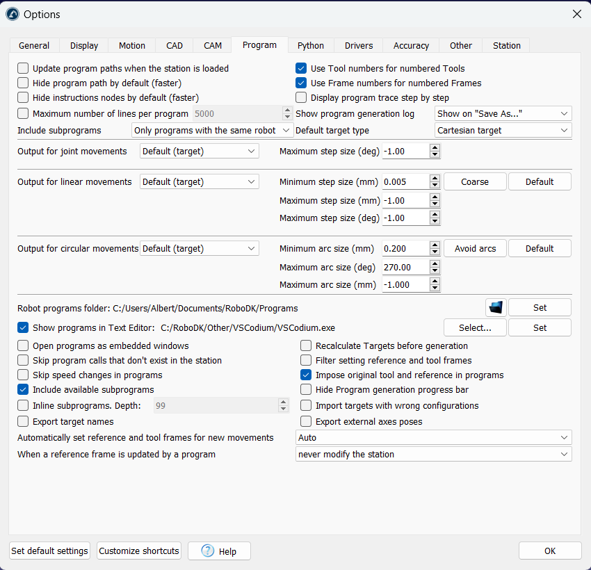
This menu allows you to customize program generation, such as:
1.Split joint movements into smaller steps.
2.Split linear movements into smaller steps.
3.Convert circular movements to small linear movements.
4.Split large robot programs into subprograms.
5.Specify the default location to save your robot programs.
6.Specify the default text editor for robot programs.
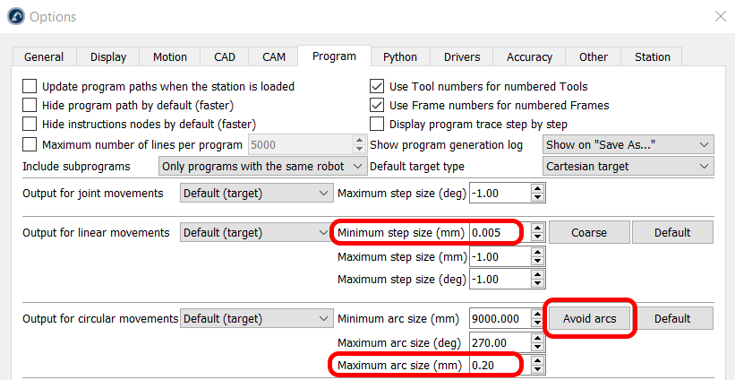
Convert circular to linear movements
You can easily convert circular moments into small linear movements when you generate programs for your robot. This is useful if your controller does not support arc movements.
Follow these steps to generate arcs as small linear movements:
1.Select Tools➔Options.
2.Select the Program tab.
3.Select Avoid arcs.
4.Specify the Maximum arc size (mm) which defines the size of the linear movements along the arc.
Split large robot Programs
Large robot programs can exceed your robot controller limitations. The controller limitations can be the file size or the number of lines per program. For example, a robot program made for robot machining or 3D printing can thousands of lines of code.
In this case it is better to split such a long program in smaller sub programs, including one main program that runs the subprograms.
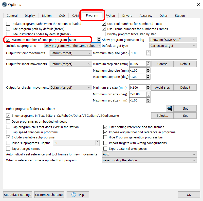
Follow these steps to automatically split a long program:
1.Select Tools➔Options➔Program.
2.Check Limit the maximum number of lines per program and provide the desired maximum of lines per program to generate per file.
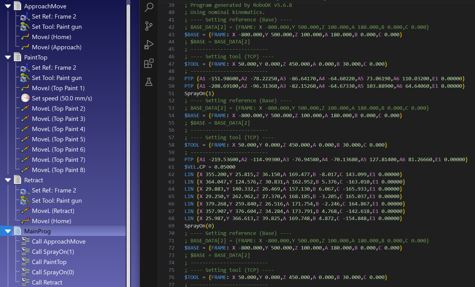
Inline subprograms
When you generate a program that calls a subprogram, RoboDK will automatically create an instruction to call that subprogram. On the other hand, you can customize program output to inline subprograms directly on your main program and prevent program calls.
Follow these steps to inline sub-programs to avoid calling offline programs by following these steps:
1.Select Tools➔Options.
2.Select the Program tab.
3.Check the option Inline subprograms.
From now on, when you generate programs that contain subprograms you will obtain the contents of these subprograms directly in the first/main program.
Post processors vs Drivers
Post processors and robot drivers use different methods to move robots. While a post processor allows you to generate programs offline, a driver allows you to have real time communication with your robot.
A post processor is used for offline programming and is responsible for converting the RoboDK robot program into the native programming language of the associated robot controller. For instance, the ABB post processor generates .mod files for IRC5 controllers. The post processor also includes program uploading to the robot controller, often by FTP. The following functionalities of a program are handled by the post processor:
1.Generate Robot Program
2.Generate Robot Program as…
3.Send Program to Robot
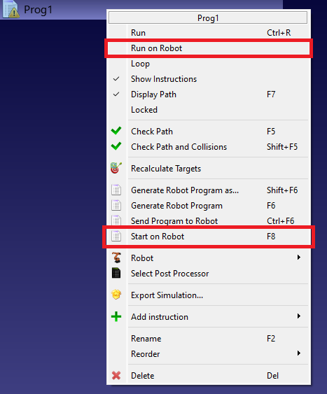
4.Start on Robot (in combination with the driver)

A robot driver enables remote control of your robot from your computer using RoboDK. This allows you to execute program instructions from RoboDK on the robot controller in real time. This includes the ability to call remote programs on the controller. For example, the ABB driver sends motion commands through socket communication. The following functionalities are handled by the driver:
1.Activate the option Run on Robot, then double click to run the program on the robot using the driver.
2.Start on Robot (in combination with the post processor)