Test ballbar
This section describes the steps required to take the ballbar measurements.
You should have 2 robot programs:
●BallbarSetup: this program allows setting the center of the ballbar test (center tool cup) at the same place where we recorded the robot joints.
●BallbarTest: this program is the circular path around the center toolcup to make the measurement acquisition with the ballbar.
To make sure that the center toolcup is at the right position we must run the program BallbarSetup. The robot will move to the center point with a linear approach. We must then place and lock the magnetic support.
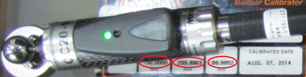
We must make sure that we have properly entered the mastering parameters of the ballbar kit (see the following image). These values must be inserted in the “Ballbar reference distance ...” from the test parameter menu. The QC20-W ballbar will be able to measure these distances plus or minus 1 mm with one micrometer accuracy. The accuracy is enough for industrial robots, but the measurement range can be limited in certain cases. For the RCS L-90, you can copy the Target distance (radius) as the reference distance is irrelevant.
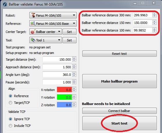
We can start with the test by selecting “Start test” (it is not required to previously select “Connect ballbar”). A new window will appear showing the ballbar connection status. If the ballbar was not detected or there are some issues, you must close the ballbar connection window, turn off the ballbar device, turn it back on and retry to start the test. If the problem persists, make sure that you have an appropriate connection (Bluetooth or USB). The RCS L-90 provides additional functionality and will indicate if the device requires homing or calibration.
Once the connection has been stablished with the ballbar, RoboDK will guide the user to follow these steps:
1.Initialise the ballbar with the distance selected for the test.
2.Move the robot to the start position (the program will pause before continuing)
3.The user must then place the ballbar on the robot.
4.Start the test by selecting OK on the computer screen. The robot won’t move until we select to continue on the robot teach pendant.
5.If everything is correct, a new window will appear showing the ballbar current measurement.
6.We can continue with the robot program to move along the path.
7.When the robot finishes the movement, we can stop the measurements (clockwise and counter clockwise).
When the test is done, RoboDK will show the result of the test and will ask the user to save a report in PDF format.
Step 4 is important to detect the beginning and end of the test. These limits are detected because the robot makes a radial movement of about 1.5 mm to trigger the start and end of measurements (at the start and end points of the path).