ISO9283 Performance Testing
Introduction
The ISO standard “ISO9283: Manipulating industrial robots - Performance criteria and related test methods” describes tests to evaluate the performance of industrial robots. Among other things, it provides procedures to properly measure robot position accuracy, repeatability and path accuracy.
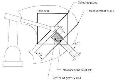
According to the ISO9283 norm, all the testing should be performed inside the so-called ISO test cube. The ISO test cube is supposed to be the largest cube that can fit inside the robot workspace. Furthermore, position accuracy and repeatability should be measured at five different configurations 30 times. It is well known that 5 configurations are not enough to provide an appropriate measurement of accuracy for modern robots.
Most robot manufacturers only provide robot positional accuracy if the robot has been calibrated, furthermore, they use at least 100 different configurations to provide appropriate position accuracy statistics. Industrial robots are highly repeatable but not accurate; therefore, the accuracy of an industrial robot can be improved through calibration.
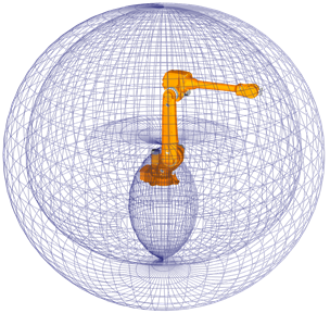
Typical robot workspace in the 80s Typical robot workspace of a modern robot
However, the ISO9283 norm is often used for repeatability and path accuracy tests even if the robot has not been calibrated.
It is recommended to watch the following video showing path accuracy tests with RoboDK: https://youtu.be/yMQjqAQY1iE.
RoboDK can also be used to calibrate the robots as well as to test their performance before and after calibration. Finally, RoboDK can also be used to test the accuracy of the robot before and after calibration through ballbar testing.
Requirements
The following items are required to install RoboDK and properly perform robot path accuracy tests:
1.One or more industrial robot arms
2.A measurement system: any laser tracker such as Leica, API or Faro and or optical CMM such as the C-Track stereocamera from Creaform should work
3.RoboDK software must be installed and an appropriate license for ISO9283 testing is required. For network licenses, an internet connection is required to check the license. To install or update RoboDK for an ISO9283 performance test:
a.Download RoboDK from the download section
https://robodk.com/download.
b.Set up the driver for the measurement system. Contact us to obtain the required driver files to the folder:
C:/RoboDK/api/.
Offline Setup
It is recommended to build a virtual environment of the real setup in RoboDK (offline setup) to prepare the path and positions for testing. This can be done before having the robot and the tracker, only using a computer with RoboDK installed. RoboDK calibration and path validation setup examples can be downloaded from the folder:
https://robodk.com/stations#filter?feature=calibration-project.
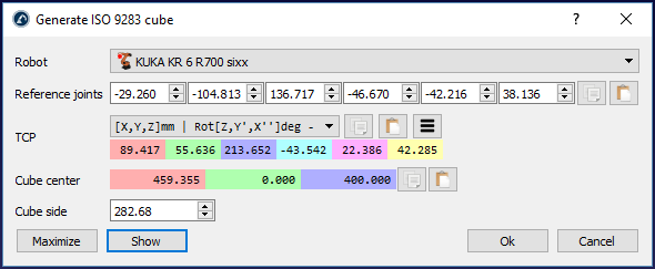
RoboDK has a utility to generate the configurations and recommended path as stated by the ISO9283 standard. To use this utility:
1.Utilities➔Create ISO 9283 cube (targets and path)
2.Enter the reference joints (robot position where the tool faces the tracker)
3.Adjust the position and size of the cube
4.Select OK
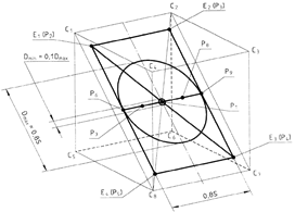
This will create the 5 targets described by the ISO norm as well as the path recommended for path accuracy testing. These targets and path remain inside a cube located in front of the robot. We can set the desired cube side as well as move the center (target “ISO p1”) and the reference joints that will define the orientation of the path. It is also possible to maximize the cube size to find the largest cube that fits in the robot workspace.
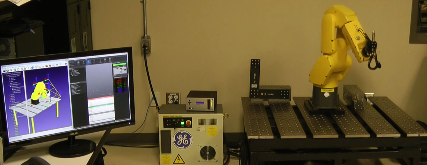
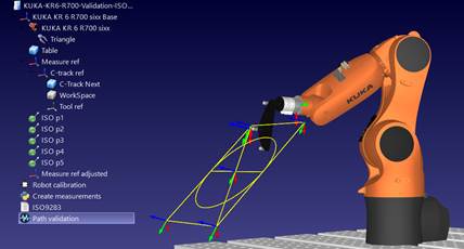
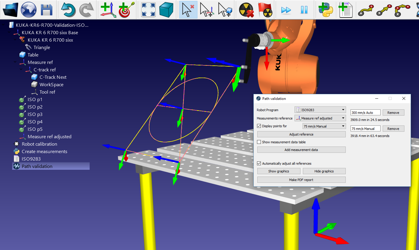
A sample station with robot calibration and robot validation options is shown in the following picture.
Position Accuracy and Repeatability
The same procedure that is used for position accuracy validation during robot calibration can also be used for position accuracy testing. Information and statistics about repeatability can also be obtained if the measurements are taken sequentially through the same group of points.
The only difference between performing only validation or calibration and validation is that the first option does not require a robot calibration license (only an ISO9283 testing license).
To perform such validations, you should select the menu:
●Utilities➔Test position accuracy & repeatability (ISO 9283)
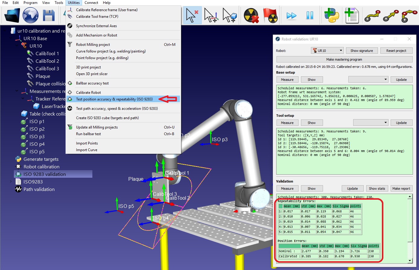
These tests require identifying the robot base frame with respect to the measurements reference frame (base setup) and the tool frame with respect to the robot flange (tool setup).
It is possible to obtain a PDF report when the position accuracy and repeatability tests are completed.
Path Accuracy
To perform path accuracy tests, it is required to have a robot program created with RoboDK, such as the ISO9283 program created by the Create ISO cube utility. We can generate the vendor-specific robot program by selecting the program and pressing F6 (or selecting Program➔Generate program). Alternatively, it is possible to use any other program created in RoboDK (such as a straight line, a circle or a square).
It is also required to have a measurement system that can track the position of the end effector and provide the position measurements with respect to a reference frame. It is required to use the base setup and tool setup procedures in RoboDK (required to perform calibration or position accuracy tests) to identify the robot base frame and tool frame.
The measurement data must be acquired while moving the robot along the program. The measurements should be recorded continuously, using the default software provided by the manufacturer of the measurement system. It is required to export the measurements as a CSV or TXT file. These files must contain XYZ position data as well as the time stamp for each measurement. Optionally, these measurements can contain the orientation of the tool with respect to the robot base.
To start a path validation project in RoboDK:
1.Select Utilities➔Test path accuracy, speed and acceleration (ISO 9283)
2.Select the program used for validation from the dropdown menu
3.Provide the reference frame used for the measurements
4.Import the measurement data by selecting Add measurement data. Alternatively, it is possible to drag & drop the CSV or TXT files containing the measurements to the Path validation window.
Finally, select Make PDF report to generate a PDF with some statistics and graphics about the path accuracy, speed and acceleration. It is possible to run the same test more than once under different conditions (different speeds, different rounding/cornering values, different payloads, …) to compare these parameters in the same report.
The measurement points can be displayed in violet. These measurements should match with the yellow path that describes the ideal path that the robot must follow. The statistics provided by RoboDK are the differences between these two paths.
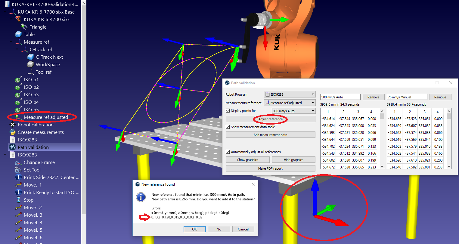
If the reference frame was not properly defined the measurement points do not match the yellow path. This can happen for several reasons, such as a bad reference frame definition or a different tool definition. In this case selecting Adjust reference will try to best fit the two paths so that the statistics provided isolate these misalignments.
Results
Once the path accuracy test is completed it is possible to obtain a PDF report by selecting Make PDF report, from the Path validation window. This will generate a PDF with some statistics and graphics about the path accuracy, speed and acceleration.
The results of the sample test prepared in the previous sections are shown in the following images. In this example, the ISO9283 program was run in two different modes:
●Manual mode at 75 mm/s speed
●Automatic mode at 300 mm/s speed
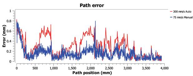
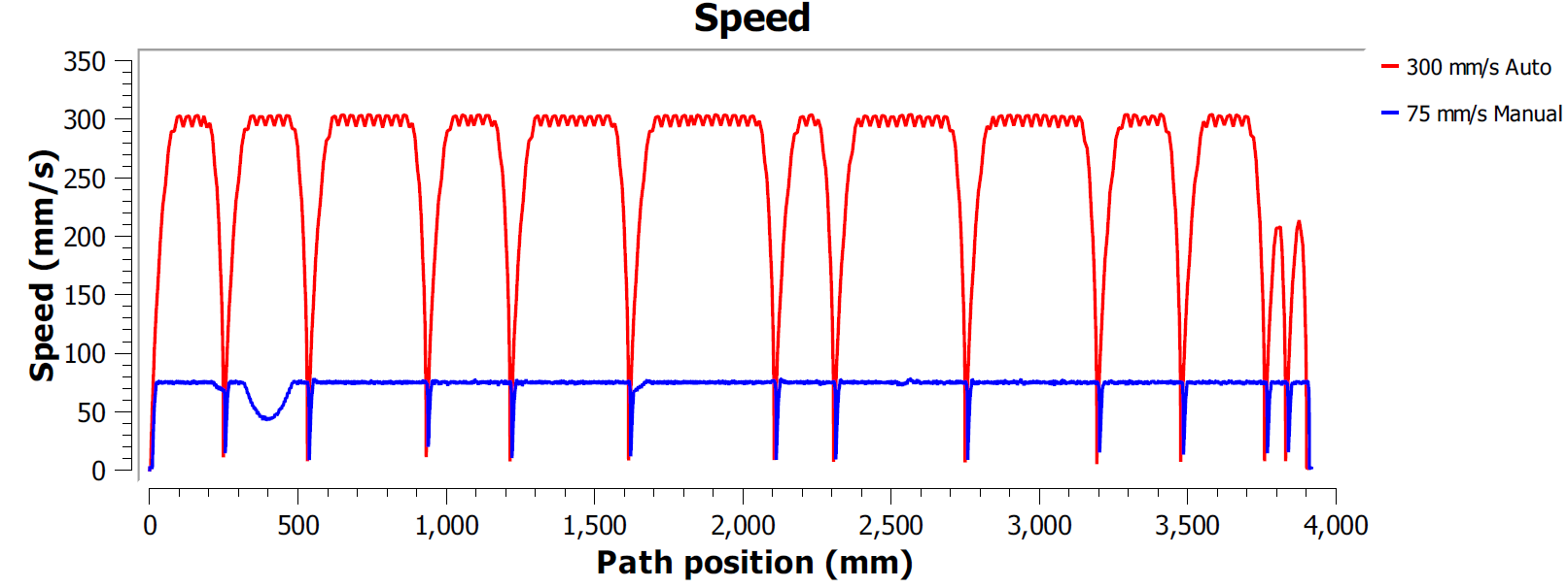
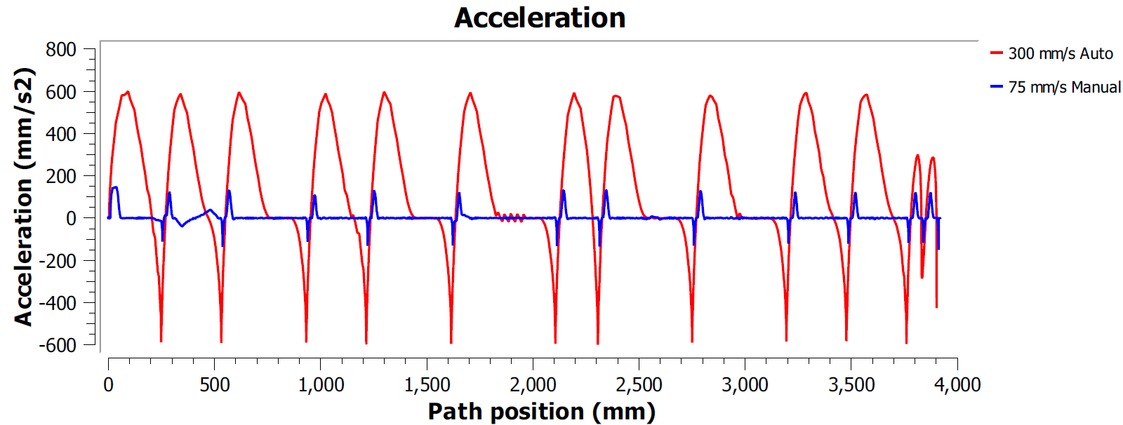
In this example, both programs were generated using the Fine accuracy option. This means that the robot will stop at every point to make the path as accurate as possible. In this case, it is typical to observe high accelerations and decelerations along the path because the speed must be zero at the end of every line or circle movement (corners).
Most robot brands offer rounding options to avoid this effect by smoothing the edges. For example, ABB calls it ZoneData and allows specifying a zone of accuracy where the controller is allowed to smooth the edges, Fanuc calls it CNT and allows specifying a percentage of smoothing proportional to the speed, KUKA option offers the $ADVANCE instruction with the C_DIS flag and Universal Robots allows specifying a blend radius to smooth the edges).
Therefore, the path accuracy test allows finding a good compromise between keeping a smooth speed while maintaining acceptable accuracy levels close to the path edges.
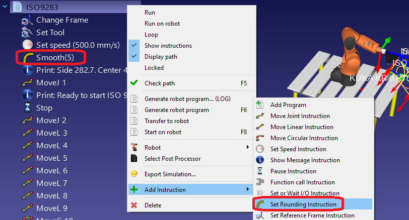
It is possible to specify the rounding parameter in RoboDK as well as the program speed. To edit a program for such a test:
1.Right click the program
2.Select Show Instructions
3.Select the first or second instruction
4.Select Program➔Set Rounding Instruction to specify a rounding accuracy
5.Select Program➔Set Speed Instruction to specify the speed