KUKA robots
RoboDK supports all KUKA robot controllers since KRC2, including KUKA KRC3 and KRC4 controllers. This documentation is based on a KRC4 controller. The KRC4 robot controller runs the Microsoft Embedded Windows 7 operating system. Previous controllers, such as KRC2, run Windows 95. The robot teach pendant shows an “HMI” which is a program that KUKA developed to run on Windows and it is the interface that the robot user must use manipulate the robot.
The following sections demonstrate typical operations using a KUKA robot teach pendant to prepare a new program in RoboDK and transfer it to the robot.
Transfer a robot program
Follow these steps to load a program form a USB disk to your KUKA KRC4 robot controller.
1.Insert the USB disk on the robot controller (it is much faster than using the teach pendant connection)
2.If we don’t see the USB disk we must enter in Administrator mode
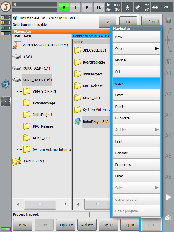
3.Select the file from the USB disk
4.Select Edit➔Copy
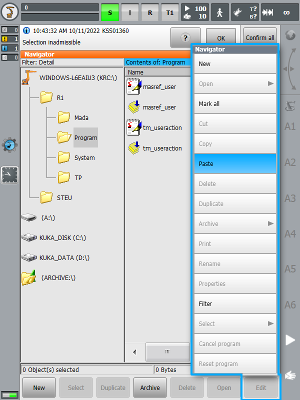
5.Select a folder in the KRC unit
6.Select Edit➔Paste
Post Processor behavior
When generating robot programs for KUKA KRC robot controllers you can define the coordinate systems ($BASE) and tools ($TOOL) given the same coordinates you entered in RoboDK or numbered coordinate systems and numbered tools respectively.
By default, RoboDK exports the full pose (XYZABC values) of your tool and coordinate system the same way you entered them in RoboDK. The following code shows an example of what RoboDK generates for a KUKA SRC robot program:
; ---- Setting tool (TCP) ----------
; TOOL_DATA[3]={FRAME: X 116.058,Y 0.0,Z 219.481,A 0.0,B 60.0,C 0.0}
$TOOL = {FRAME: X 116.058,Y 0.0,Z 219.481,A 0.0,B 60.0,C 0.0}
; $TOOL=TOOL_DATA[3]
; ----------------------------------
; ---- Setting reference (Base) ----
; BASE_DATA[1]={FRAME: X 640.289,Y -290.0,Z 0.0,A 90.0,B 0.0,C 0.0}
$BASE = {FRAME: X 640.289,Y -290.0,Z 0.0,A 90.0,B 0.0,C 0.0}
; $BASE = BASE_DATA[1]
; ----------------------------------
On the other hand, if you prefer linking your tool ($TOOL variable) and coordinate system ($BASE variable) to numbered tools and reference frames, you can change the following variables in your post processor:
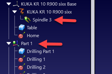
●FRAME_INDEX: Set this variable to True to link your coordinate system to a numbered base frame. You should make sure your reference frame has a number in your RoboDK station as shown in the following image.
●TOOL_INDEX: Set this variable to True to link your tool to a numbered tool. You should make sure your tool has a number in your RoboDK station as shown in the following image.
Start a robot program
Follow these steps to start a robot program on your KUKA KRC4 controller.
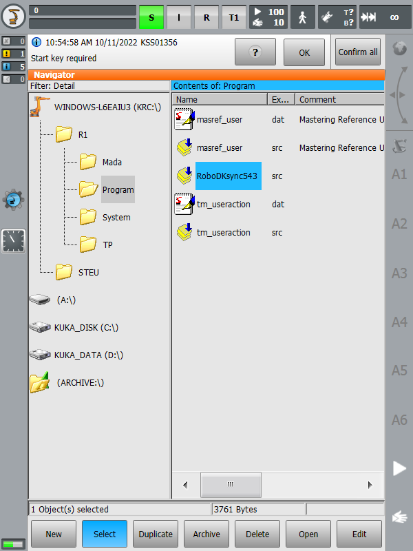
1.Select a program from the KRC memory unit
2.Select Select on the screen
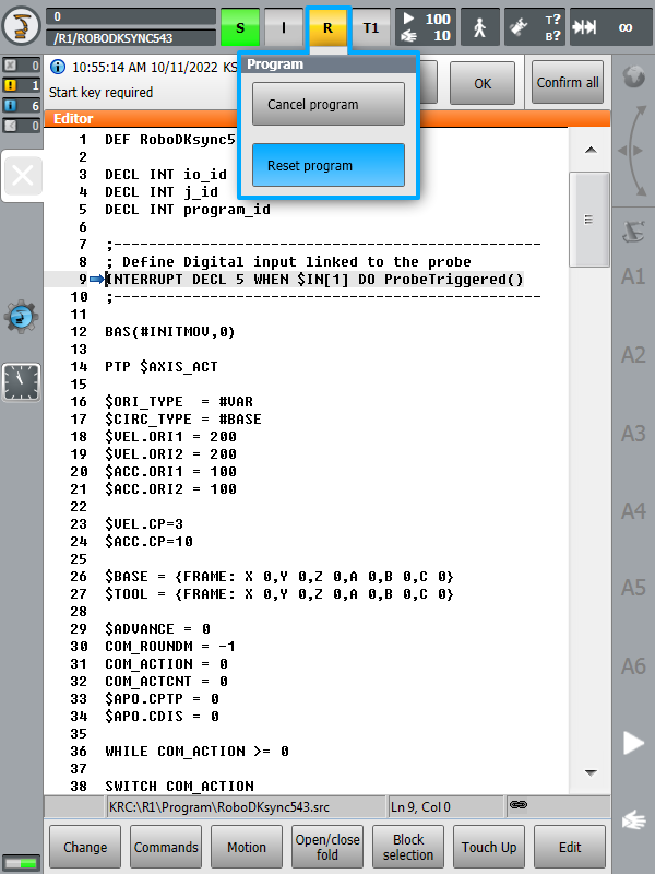
3.Select the button “R” (top) and Reset program
4.Start the program by selecting green “Play” button on the teach pendant
Retrieving the TCP
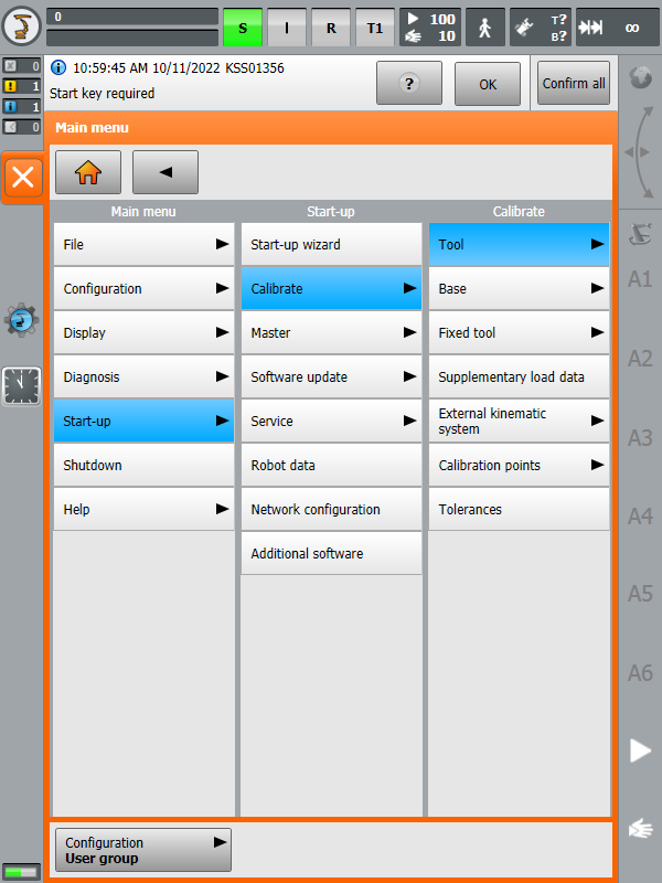
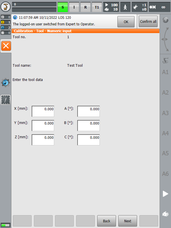
The following steps allow you to create or modify robot tools (TCP) from your robot controller, also known as $TOOL in KUKA KRC robot programming):
1.Select 
2.Select a tool and edit or retrieve the X,Y,Z position of the TCP.
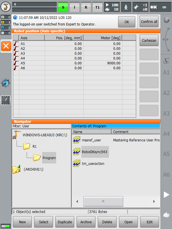
Retrieving the robot joints
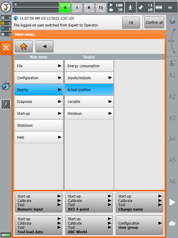
The following steps allow you to retrieve the robot joints from your robot:
1.Select
2.Select Joints mode and use the left column to take the robot joints
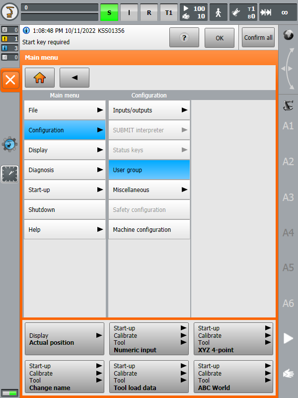
Administrator mode
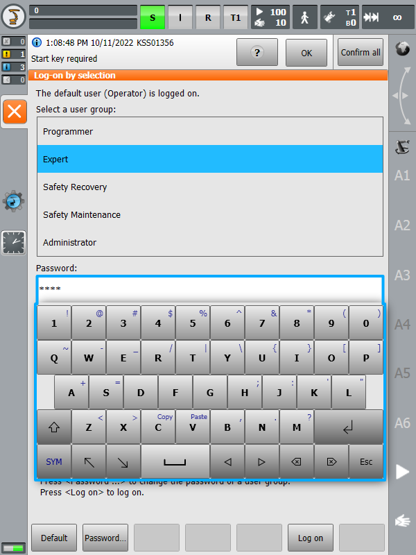
Some menu sections require “Expert” or “Administrator” rights. The following steps allow entering in “Expert” mode:
1.Select
2.Select Expert (or Administrator).
3.Enter the password if required (the default password is “kuka”)
RoboDK driver for KUKA
Robot drivers provide an alternative to Offline Programming (where a program is generated, then, transferred to the robot and executed). With robot drivers, it is possible to run a simulation directly on the robot (Online Programming). More information available in the Robot Drivers section.
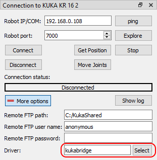
You can establish a connection between RoboDK and your KUKA controller to move the robot automatically from your computer. This allows using the RoboDK Run on robot option for online programming and debugging. The connection can be established through a standard Ethernet connection (TCP/IP).
If you don’t use a recent version of the RoboDK you may be using the legacy driver (apikuka, based on the KUKAVARPROXY project). To use the current driver, make sure that the kukabridge driver is selected in the More options section of the Connection to Robot window.
Follow these steps to set up the RoboDK driver for KUKA:
1.Get the latest C3 Bridge installer file (c3setup executable) from this link.
2.Using the KUKA HMI, copy the c3setup.exe installer file to the desktop of your controller or a folder of the control system.
3.Connect a mouse (optional, but recommended).
It is possible to plug USB devices to the teach pendant or the controller (reboot is not required).
Alternatively, it is possible to establish a remote desktop connection.
These steps can also be accomplished using the teach pendant’s touch screen and the virtual keyboard.
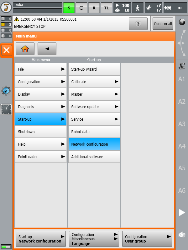
4.Using the KUKA HMI application it is possible to open the main menu using the KUKA button
a.
b.
5.Locate the previously copied c3setup-X.Y.Z.exe (where X.Y.Z is the Kukabridge release version, e.g. 1.7.1) file and run it. Follow the instructions of the installer.
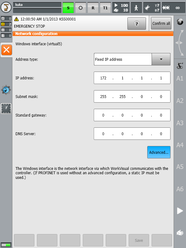
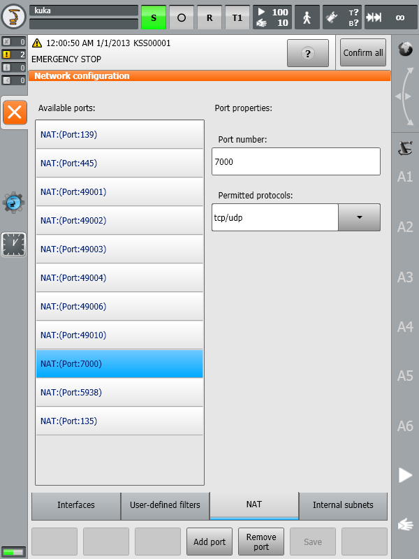
6.Allow port 7000 (or another port if port 7000 is busy, see note below)for TCP/UDP communication (this step is not required on KUKA KRC2 controllers):
a.Restore the HMI.
b.
c.NAT➔Add port➔Port number 7000
d.Set permitted protocols: tcp/udp
7.Launch the C3 Bridge Server from the desktop shortcut or the Start Menu item (you can skip this step in case you selected Run C3 Bridge Server at the last installation step).
8.To start C3 Bridge Server automatically at system startup, copy the application shortcut from the desktop to the Startup folder of the Start Menu.
The C3 Bridge Server is now ready. You can leave this program running. This server allows you to exchange global variable values between the KUKA control system and the remote PC, download and upload KRL programs, control the execution of KRL programs, and more.
Further configuration of the control system can be done in two ways: automatically using the interactive mode of the kukabridge driver (KRC4 only) and manually by editing the robot control system files in KUKA HMI. Let's take a look at both approaches.
Changing the C3 Bridge Server port number
The C3 Bridge Server stores its settings in the Windows Registry. Follow these steps to change the network port:
1.Terminate the C3 Bridge Server.
2.Open the Registry Editor and navigate to HKEY_CURRENT_USER\SOFTWARE\C3 Bridge Interface.
3.Change the value of the NetworkTcpPort key to a value other than 7000 (for example, 7001).
4.Start the C3 Bridge Server again and repeat step 6 of the previous section (open access to the appropriate port).
Newer versions of the C3 Bridge Server (1.7.1 and higher) support command line options. In particular, the server port can be changed by running the application with the -tcpPort parameter. For example:
c3bridge.exe -tcpPort 7001
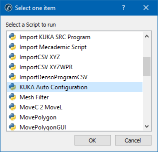
Automatic configuration using a script
The script KUKA_Auto_Configuration.py in the folder C:\RoboDK\Library\Scripts can be used to perform automatic configuration of the KUKA control system. In that case, the current RoboDK station must contain at least one KUKA robot with the correct IP address and port in the Connection to Robot window. The script can be called from the menu Tools➔Run Script or by the Shift+S hotkey.
Automatic configuration
Prerequisites: RoboDK version 5.5.2 or higher, Windows operating system, installation path C:\RoboDK.
1.Open command shell with START➔All programs➔ Accessories➔Command Prompt
or START➔Run➔cmd.
2.Change directory to C:\RoboDK\bin and launch kukabridge.exe by executing following commands:
c:
cd C:\RoboDK\bin
..\api\Robot\kukabridge.exe
3.Now KUKA Bridge Driver is running in interactive mode.
4.Establish a connection to the control system by entering CONNECT <robot IP address> <port> <number of robot axes>, e.g:
CONNECT 172.1.1.10 7000 6
5.If successful, you will see the following output:
SMS:Connecting
Connected
SMS:Working...
SMS:Ready
6.Request current robot joint position by typing the CJNT command:
CJNT
SMS:Working...
JNTS 0.00000 0.00000 0.00000 0.00000 0.00000 0.00000 0.00000 0.00000 0.00000 0.00000 0.00000 0.00000
SMS:Ready
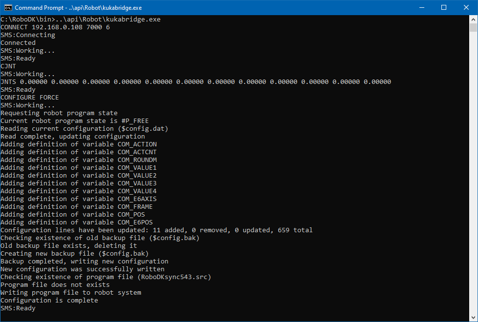
7.Perform automatic configuration with the CONFIGURE FORCE command:
CONFIGURE FORCE
SMS:Working...
Requesting robot program state
Current robot program state is #P_FREE
Reading current configuration ($config.dat)
Read complete, updating configuration
Adding definition of variable COM_ACTION
Adding definition of variable COM_ACTCNT
Adding definition of variable COM_ROUNDM
Adding definition of variable COM_VALUE1
Adding definition of variable COM_VALUE2
Adding definition of variable COM_VALUE3
Adding definition of variable COM_VALUE4
Adding definition of variable COM_E6AXIS
Adding definition of variable COM_FRAME
Adding definition of variable COM_POS
Adding definition of variable COM_E6POS
Configuration lines have been updated: 11 added, 0 removed, 0 updated, 659 total
Checking existence of old backup file ($config.bak)
Old backup file exists, deleting it
Creating new backup file ($config.bak)
Backup completed, writing new configuration
New configuration was successfully written
Checking existence of program file (RoboDKsync543.src)
Program file does not exists
Writing program file to robot system
Configuration is complete
SMS:Ready
8.Now your robot is ready to work, all you have to do is select and run the program RoboDKsyncVER.src (where VER is the sync program version, e.g. 543).
Manual configuration
The next steps are to manually set up the main program that will handle the robot movements:
1.Add the declaration of the following global variables:
To do so, locate and modify the file “KRC:\R1\SYSTEM\$CONFIG.DAT” via KUKA HMI. The folder “KRC:\R1\” can also be accessed from the C:\ drive at the following Windows path: “C:\KRC\ROBOTER\KRC\”.
INT COM_ACTION=0
INT COM_ACTCNT=0
REAL COM_ROUNDM=0
REAL COM_VALUE1=0
REAL COM_VALUE2=0
REAL COM_VALUE3=0
REAL COM_VALUE4=0
DECL E6AXIS COM_E6AXIS
DECL FRAME COM_FRAME
DECL POS COM_POS
DECL E6POS COM_E6POS
2.Copy the KUKA SRC program RoboDKsyncVER.src to the folder KRC\R1\PROGRAM. The VER suffix in the file name denotes the version of the program (for example, RoboDKsync543.src).
3.Manually start the RoboDKsyncVER.src program to make the robot listen for commands coming from the computer.
If the RoboDKsyncVER.src program is not running, RoboDK will still be able to read the robot joints if the C3 Bridge Server is running in the robot controller.
Legacy driver for KUKA (Kukavarproxy)
The legacy KUKA driver is called apikuka and is used in conjunction with KUKAVARPROXY. This solution is now obsolete and is being discontinued by RoboDK. If you want to use this driver, make sure it is selected in the More options section of the Connection to Robot window.
Follow these steps to set up the legacy driver for KUKA:
1.Connect a mouse (optional, but strongly recommended).
It is possible to plug USB devices to the teach pendant or the controller (reboot is not required).
Alternatively, it is possible to establish a remote desktop connection.
These steps can also be accomplished using the teach pendant’s touch screen and the virtual keyboard.
9.Using the KUKA HMI application it is possible to open the main menu using the KUKA button
a.
b.
10.Copy the KUKAVARPROXY folder on the Desktop (or somewhere in the controller PC)
11.Allow port 7000 for TCP/UDP communication (this step is not required on KUKA KRC2 controllers):
a.Select the HMI.
b.
c.NAT➔Add port➔Port number 7000
d.Set permitted protocols: tcp/udp
12.Start the KUKAVARPROXY.EXE program on the robot controller (running on Windows).
13.The following steps allow starting the driver automatically on the controller on reboot (recommended):
a.Create a shortcut of the KUKAVARPROXY.EXE file
b.Select Windows START➔All programs➔Right click startup➔Open
c.Paste the shortcut in the startup folder
The KUKAVARPROXY server is now ready. You can leave this program running. This server allows exchanging global variables from the KUKA controller to the remote PC.
The next steps are to set up the main program that will handle the robot movements:
1.Add the declaration of the following global variables:
To do so, locate and modify the file “KRC:\R1\SYSTEM\$CONFIG.DAT” via KUKA HMI. The folder “KRC:\R1\” can also be accessed from the C:\ drive at the following Windows path: “C:\KRC\ROBOTER\KRC\”.
INT COM_ACTION=0
INT COM_ACTCNT=0
REAL COM_ROUNDM=0
REAL COM_VALUE1=0
REAL COM_VALUE2=0
REAL COM_VALUE3=0
REAL COM_VALUE4=0
DECL E6AXIS COM_E6AXIS
DECL FRAME COM_FRAME
DECL POS COM_POS
DECL E6POS COM_E6POS
2.Copy the KUKA SRC program RoboDKsyncVER.src to the folder KRC\R1\PROGRAM. The VER suffix in the file name denotes the version of the program (for example, RoboDKsync543.src).
3.Manually start the RoboDKsyncVER.src program to make the robot listen for commands coming from the computer.
If the RoboDKsyncVER.src program is not running, RoboDK will still be able to read the robot joints if the KUKAVARPROXY program is running in the robot controller.
Troubleshooting
This section explains how to determine, diagnose, and fix issues that you might encounter when you use KUKA robot drivers with RoboDK.
Checking the availability of port 7000
You should enter the Expert user group on the KUKA controller to troubleshoot issues with port 7000.
1.
2.
3.Open command shell with START➔All programs➔ Accessories➔Command Prompt
or START➔Run➔cmd
4.Request a list of all connections and listening ports using the command:
netstat -a -b -n -o -p TCP | findstr :7000
5.If the response did not contain any strings, then port 7000 is free and can be used for driver operation. Subsequent steps can be skipped.
6.If the response to the command from step 4 looked like this:
TCP 0.0.0.0:7000 0.0.0.0:0 LISTENING 1840
7.The last number in the line above is the process identifier (PID). It can be used to get information about the process name using the following command (you should use your number instead of 1840):
tasklist /fi "PID eq 1840"
8.The result of the tasklist command contains information about the process that is listening on port 7000. Sample output:
Image Name PID Session Name Session# Mem Usage
========================= ======== ================ =========== ============
c3bridge.exe 1840 Console 1 5,912 K
9.If the port is occupied by KukavarProxy.exe or c3bridge.exe processes, then the system is ready to work with the selected driver. If the port is occupied by some other application, it is necessary to terminate it or change the port number for the C3 Bridge Server.
Uninstalling legacy driver
If you have been using KUKAVARPROXY and wish to upgrade to C3 Bridge Server, no specific uninstallation procedure is required. Minimize the KUKA HMI, close the KUKAVARPROXY and make sure it is not loaded automatically at system startup (no shortcut in START➔All programs➔Startup). It is not necessary to delete the KUKAVARPROXY executable file.
Configuration error
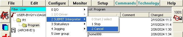
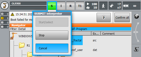
Procedures for automatic or manual configuration of the control system may fail. Most often this is due to the inability to overwrite the $config.dat file. This file can only be edited by a user with advanced privileges (expert). An additional condition is to stop all interpreters: robot and submit. To stop the robot interpreter, simply cancel any selected program, or select no programs if the control system has just been loaded. To cancel the submit interpreter, use the HMI as shown in the figures below for KRC2 and KRC4 systems, respectively:
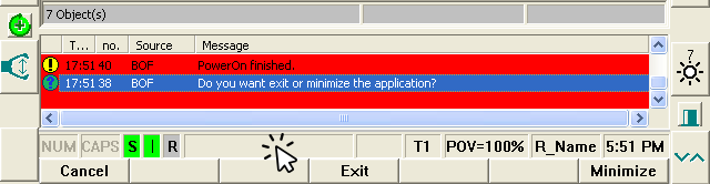
In case the $config.dat file is still locked after stopping all interpreters, you can completely stop the execution of the software part of the robot control system. In the KRC2 system, click on the rectangular area next to the status indicators (S I R) and click the Exit button:
In the KRC4 system, click on the green robot icon in the tray area and select Stop KRC:
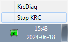
After stopping the control software, the file C:\KRC\ROBOTER\KRC\R1\System\$config.dat can be modified using any text editor. Perform a reboot of the operating system to apply the changes.
External axes
You should be able to use the driver and the post processor with KUKA robot controllers even if you have external axes such as a turntable. We recommend you use a numbered coordinate system or a coordinate system with the correct machine definition that is already defined on your robot controller.
The following files from your KUKA robot controller will help you understand how the KUKA system is built:
●KRC\R1\System\$config.dat
●KRC\R1\System\bas.src
●KRC\R1\Mada\$machine.dat
If you have a turntable, the position of the origin of the turntable should be defined in a MACHINE_DEF variable of the config.dat file. Whoever installed the system should have provided an example to generate a program using a synchronized turntable based on the BAS function.
For example, when you call the BAS function in your SRC file using the ex_BASE flag and a certain index, such as index 9:
BASE_DATA[9] = {FRAME: X 0, Y 0, Z 0, A 0, B 0, C 0}
BAS(#ex_BASE,9)
You are telling you want to use index 9 of your MACHINE_FRAME_DAT. You should also look at the BAS and EX_BASE definitions to see what machine index (MACH_IDX) your controller is referring to by default. The BASE_DATA array defined just before calling the BAS function in your SRC file could be just the offset of your fixture mounted on your turntable.
You may need to manually change the $BASE variable with your post processor or driver to be the origin of your turntable if you have a turntable synchronized with your robot arm.
For example, if you have the BASE_DATA index 9 available, you should use the following code with your driver.
;--------
; Replace this the $BASE definition by the following 2 lines
; to make the KUKA RoboDKSynch driver work with external axes:
; $BASE = {FRAME: X 0, Y 0, Z 0, A 0, B 0, C 0} ; Comment this line
BASE_DATA[9] = {FRAME: X 0, Y 0, Z 0, A 0, B 0, C 0}
BAS(#ex_BASE,9)
; the BAS ex_BASE function links to a fixed MACHINE_DEF index
; visible in the BAS function
; The previous two lines are equivalent to the following,
; if the BAS function uses index 2 for the Machine definition
; BASE_DATA[9] = {FRAME: X 0, Y 0, Z 0, A 0, B 0, C 0}
; $BASE=EK(MACHINE_DEF[2].ROOT,MACHINE_DEF[2].MECH_TYPE,BASE_DATA[9])
;--------
$BASE=EK(EX_AX_DATA[1].ROOT,EX_AX_DATA[1].EX_KIN,EX_AX_DATA[1].OFFSET)
For the post processor you could replace the previous line in the setFrame function of your post processor to use this $BASE definition if you want to account for the offset between the turntable and your fixture:
$BASE=EK(MACHINE_DEF[2].ROOT, MACHINE_DEF[2].MECH_TYPE, {%s})' % self.pose_2_str(pose)
Alternatively, when you use the driver you can isolate the coordinate system by following the procedure described below (so you don’t need to perfectly match the kinematics of your external axes in RoboDK).
For example, to be able to use the RoboDK driver by default, the kinematics of your external axes defined in the robot controller should match the kinematics created in RoboDK. Also, if you have a turntable, the root point of the turntable should match the position of the turntable defined in RoboDK.
Follow these steps to use the driver using a known coordinate system:
1.Select Tools➔Options➔Drivers tab.
2.Check the option Provide Cartesian coordinates with respect to the reference.
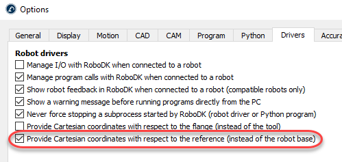
3.Replace the $BASE variable of your RoboDKsync.src program file by the coordinate system you want to use.
For example, if you want to use the base reference frame number 5, the RoboDKsync.src file should look like this (the first line is commented, you should find it around line 25):
; $BASE = {FRAME: X 0,Y 0,Z 0,A 0,B 0,C 0}
$BASE = BASE_DATA[5]
This coordinate system must have been defined in the KUKA robot controller and RoboDK will not override this value.
Robot calibration
You can use RoboDK to calibrate KUKA robots that have already been calibrated by KUKA using the Absolute Accuracy option. However, you should make sure to deactivate this option in the KUKA robot controller. When you calibrate a KUKA robot that has already been calibrated by KUKA using the Absolute Accuracy option it is important to deactivate this option so you can calibrate it using RoboDK.
To deactivate KUKA’s Absolute Accuracyyou should set variable DEACTIVATE_ABS_ACCUR to TRUE. You can find this variable in the file KRC:\STEU\MADA\$custom.dat (around line 73).
You can make sure that KUKA’s absolute accuracy option has been properly deactivated by moving the robot to a known position (for example, move the robot axes of the real robot and in RoboDK to the home position) and make sure the Cartesian position displayed by the robot controller matches the same Cartesian position displayed by RoboDK.