RoboDK TwinTrack
RoboDK TwinTrack allows you to easily mimic and replay human movements with a robot for fast and reliable automation. You can manually teach your robot the path to follow the same way you would manually perform a manufacturing operation with your hands, you can track it and replay it with a robot.
Introduction
RoboDK TwinTrack offers a new way to teach robots by demonstration and can be used for many manufacturing applications like painting, polishing, deburring, dispensing, welding etc …
One advantage of using a teach by demonstration method such as TwinTrack is that you can mimic the manufacturing operation with your and the robot will replay the same motion. This method of robot programming does not require you to use 3D models. It does not require an operator to use a computer either. This will allow you to save a significant amount of time and you can start programming robots faster.
RoboDK TwinTrack requires a 6D measurement system and a handheld probe or a handheld manufacturing tool that allows you to mimic the manufacturing operation with your hands.
RoboDK supports over 1000 robots from 90 different robot manufacturers. This means you can program any robot arm supported by RoboDK. You can also create your own robots and mechanisms.
With the TwinTrack and RoboDK calibration tools you can create highly accurate robot programs. With a good measurement system, you can reach up to 0.150 mm position accuracy. The level of accuracy highly depends on the quality and size of the robot. By using RoboDK calibration tools you can accurately create your digital twin.
Requirements
It is required to install the RoboDK TwinTrack Add-in and have a supported measurement system to use the TwinTrack tools.
Make sure to have the following:
1.One or more industrial robot arms.
2.A supported measurement system (6 DOF). Supported measurement systems include:
a.HTC Vive Trackers (SteamVR)
b.Full Virtual Reality kit (SteamVR)
c.Laser tracker with 6 DOF capability and supported RoboDK driver
d.Creaform C-Track
e.OptiTrack Camera system (it is recommended to use 4 PrimeX13 for best accuracy)
1.RoboDK software must be installed and an appropriate license for TwinTrack must be installed.
2.You need compatible robot drivers for your robot controller if you want to automatically run robot programs.
3.Install the TwinTrack RoboDK Add-in:
a.Download the TwinTrack Add-in (.rdkp file).
b.Double click the file to install the Add-in and open it in RoboDK.
c.If you don’t see the TwinTrack menu: select Tools➔Add-in Manager and double click on TwinTrack to see the TwinTrack menu on the top right.
Setup with SteamVR and HTC Vive Trackers
This section guides you through the steps to configure SteamVR. You can use a custom-made tool with a tracker to mimic your manufacturing operations with your hand so your robot can replay the same motion.
RoboDK TwinTrack supports Virtual Reality systems and all trackers supported by SteamVR, including HTC Vive Trackers from v1 to v3.
Follow these steps to configure your SteamVR system for TwinTrack:
1.Install Steam if you have not done it yet, you may need to create an account with Steam.
2.Install SteamVR, this is a Steam extension that adds support to Virtual Reality and 6D Tracking.
3.Remove the need to have Virtual Reality headset if you don’t have it or you don’t need it by following these steps:
a.Edit the following file using a text editor:
C:/Program Files (x86)/Steam/steamapps/common/SteamVR/drivers/null/resources/settings/
default.vrsettings
And set:
“enable”: true, (default is false)
b.Edit the following file using a text editor:
C:/Program Files (x86)/Steam/steamapps/common/SteamVR/resources/settings/
default.vrsettings
And set:
“requireHmd”: false, (default is true)
“forcedDriver”: “null”, (default is empty “”)
“activateMultipleDrivers”: true, (default is false)
Close SteamVR and open again.
4.Open SteamVR and follow the instructions to set up your system. You can accept all default settings if you are not using a VR headset.
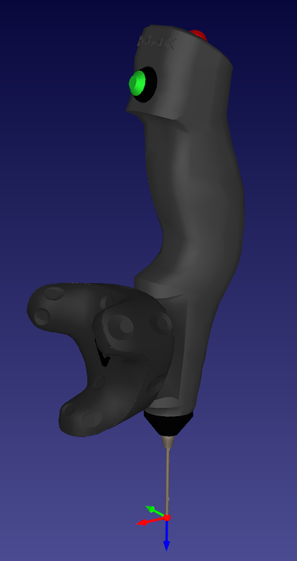
5.Pair a tracker as a probe:
a.Hold the power button on the Tracker for 2 seconds to turn it on (the tracker light should turn blue for a non-paired tracker)
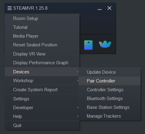
b.Open the Menu➔Devices➔Pair Controller
c.Select the option: HTC ViveTracker. The tracker should be paired automatically, and the tracker light should turn green.
To remove the link you can hold the power button for 2 seconds and the light should turn blue (it may blink).
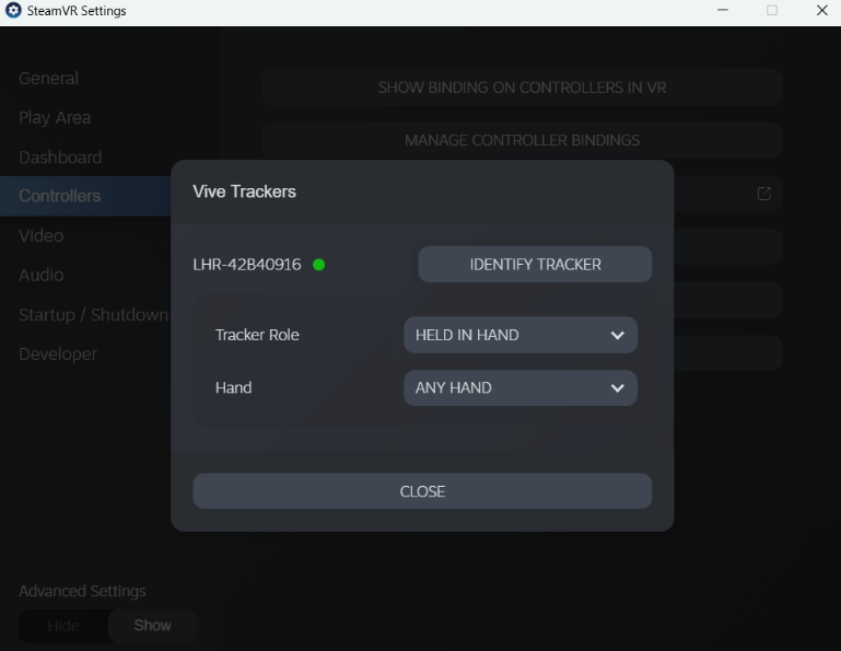
6.Set the tracker role as Held in hand.
a.Select the SteamVR menu➔Settings
b.Select Controllers
c.Select Manage Trackers
d.Set Tracker Role➔Held in hand
e.Set to Any hand (default)
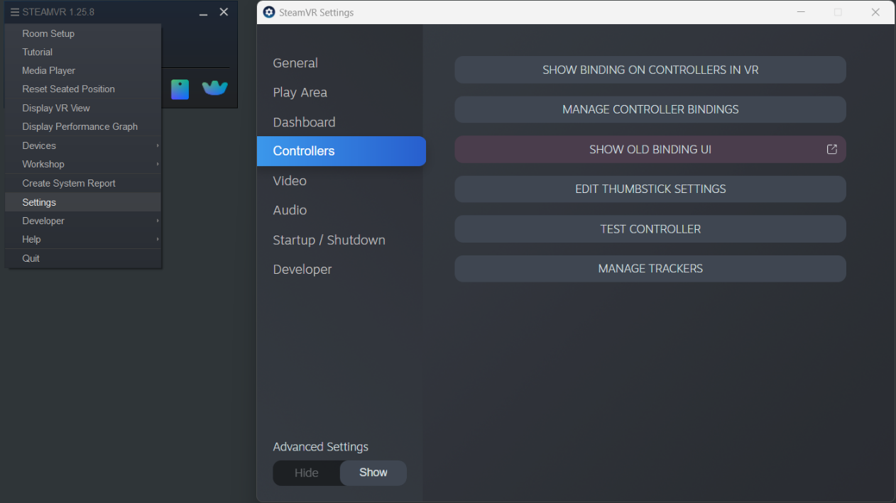
7.Customize your controller bindings:
a.Select SteamVR➔Settings
b.Set Advanced Settings➔Show
c.Select Controllers
d.Select Show Old Bindings UI
e.Select RoboDK
f.Select the Current controller and set to Vive Tracker in Hand (unless it was already set)
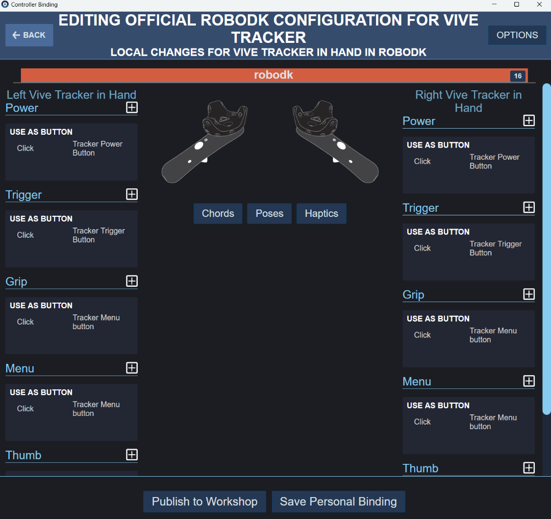
g.Select Edit in the current binding
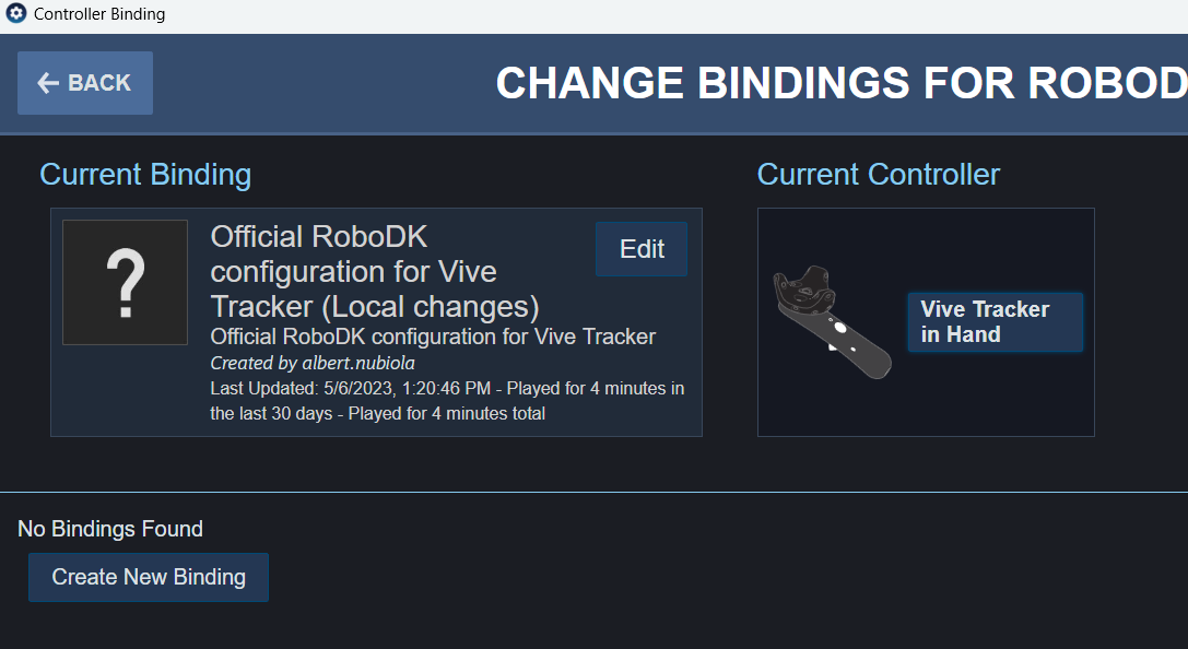
h.You should see the default bindings for the tracker.
Setup
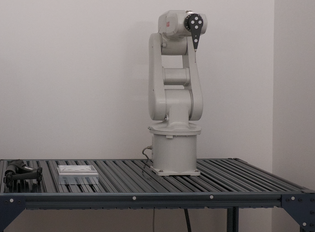
To use the TwinTrack system you need to load your robot in RoboDK and connect to the robot and the measurement system. We can optionally model the cell by adding the 3D models of objects and tools. This will help prevent collisions.
8.Load the robot:
a.Select File➔Open online library. The online library will show up in RoboDK.
b.Use the filters to find your robot.
c.Select Download to automatically load the robot in your RoboDK station.
d.Alternatively, download the robot file directly from the online library and open the file with RoboDK (.robot file).
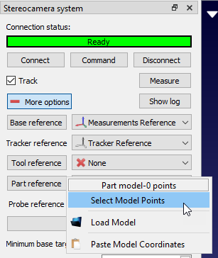
9.Connect the measurement system:
a.Connect the measurement system to your computer.
b.Select Connect and connect to your measurement system. Make sure required software is also installed. You may have to the IP of the tracker depending on the measurement system you use.
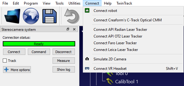
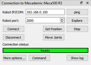
10.Connect the robot:
a.Select Connect➔Connect robot.
b.Enter the robot IP and port.
c.Select Connect.
System Calibration
This section will guide you to calibrate your robot and the probe. This step only needs to be done once but it is important to obtain good accuracy results.
Before starting the calibration, it is recommended to load the 3D models of your cell. This will help you automatically avoid collisions during the calibration process. If you don’t have the 3D models of each component you can simply load planes boxes and spheres to represent the areas you don’t want to access.
Robot calibration
This section describes how to automatically calibrate your robot using RoboDK TwinTrack and your measurement system. Robot calibration allows you to improve robot accuracy to up to 0.150 mm when you generate programs offline or using TwinTrack teach by demonstration tools in RoboDK (the level of accuracy highly depends on the quality and size of the robot).
It is recommended to perform the robot calibration after you build your robot cell or you make major modifications (such as changing the payload of your tool). This helps obtaining the best accuracy.
Before you begin the calibration, you can model your cell in RoboDK to automatically avoid collisions. You can use basic geometries such as planes or cubes to avoid unwanted areas. You can also limit the joint space of the robot.
You can select TwinTrack➔Calibrate robot to start the robot calibration procedure.
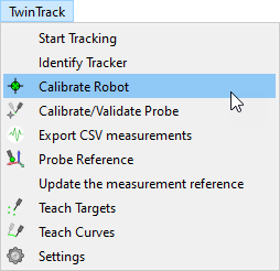
This operation will guide you to calibrate the robot, including the automatic generation of points for calibration and validation. RoboDK can automatically generate points that are visible by the tracker.
The robot calibration procedure requires taking around 200 measurements. The procedure starts by taking some measurements around the home position of the robot.
Once the setup is ready and the communication with the robot are properly stablished, the calibration procedure should take 15-30 minutes.
The system requires no special fixtures or accessories, it simply tracks the position of the tool with respect to the tracker reference.
It’s fine if you miss some measurements because the targets are not visible.
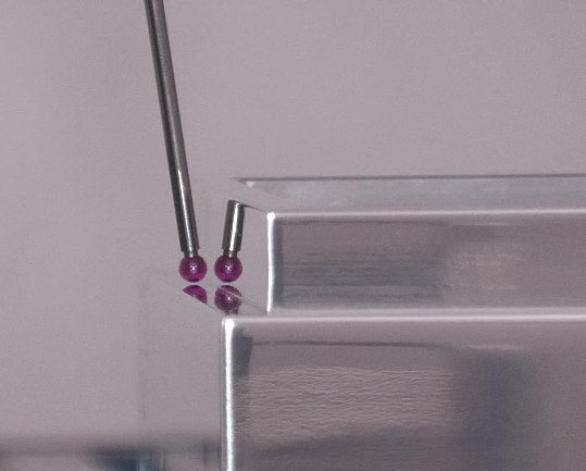
Probe calibration
It is important to properly calibrate the tip of your probe and make sure it is accurate within your desired tolerances.
Calibrating the tip of the probe is accomplished by moving the tip around a static point.
Select TwinTrack➔Calibrate/Validate Probe Tip to start the tool calibration.
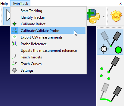
In this case, because we are using the Creaform HandyProbe, you can calibrate the probe using Creaform VXElements software and validate it using RoboDK.
To validate the tip of your probe you simply need to move around a static point and RoboDK will display the accuracy.
Programming offline
You can use the teach by demonstration features without a real robot. This means you can simulate and program your robot offline only with your measurement system before you have access to the real robot.
You simply need a part with a well-defined coordinate system that you can use as a reference.
Once you have the measurement system and your part ready you can follow these steps to define the coordinate system of your measurement device:
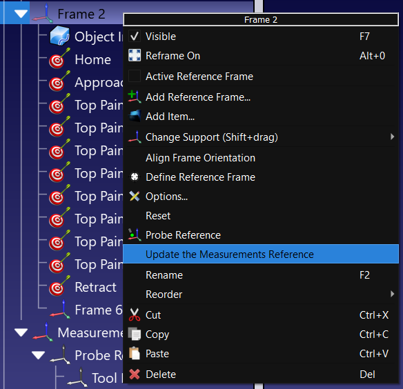
1.Right click the coordinate system of your part (or the coordinate system of jig it is attached to).
2.Select Update the Measurements Reference.
3.Follow the instructions on the screen to teach 3 points that define the coordinate system: the origin, a point on X+ and a point on Y+.
The measurement system will be updated accordingly, and you can proceed to teach points, curves or other coordinate systems.
Teach Targets
With RoboDK TwinTrack you can create robot targets manually by teaching points with your probe.
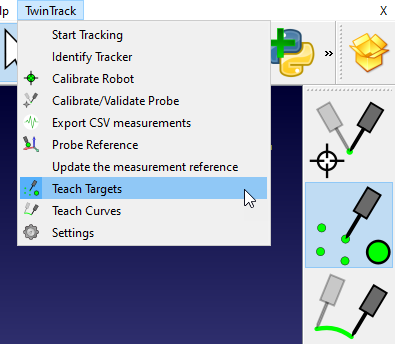
You can start the teach targets mode by selecting TwinTrack➔Teach Targets. This button is also available in the TwinTrack toolbar by default.
RoboDK calculates and displays the robot position in real time based on the position of your hand. You can easily see what areas are reachable by your robot.
With the create targets option you will be teaching one target with every push of a button. Once you want to create a program, you can push the second button of your probe and RoboDK will simulate the program:
●First button: teach targets.
●Second button: create and simulate the program in RoboDK.
●Hold the second button: run the program on the robot.
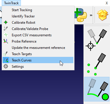
Teach Curves
With RoboDK TwinTrack you can create robot paths or curves manually with your probe.
You can start the teach targets mode by selecting TwinTrack➔Teach Curves. This button is also available in the TwinTrack toolbar by default.
RoboDK calculates and displays the robot position in real time based on the position of your hand. You can easily see what areas are reachable by your robot.
You can create a curve by holding the first button of your probe. Once you want to create a program, you can push the second button of your probe and RoboDK will create and simulate the program:
●Hold the first button: teach curves/paths.
●Second button: create and simulate the program in RoboDK.
●Hold the second button: run the program on the robot.
Teach a coordinate system
With RoboDK TwinTrack you can probe and locate your coordinate systems (or reference frames) to locate objects in the robot workspace.
Right click your coordinate system and select Probe Reference.
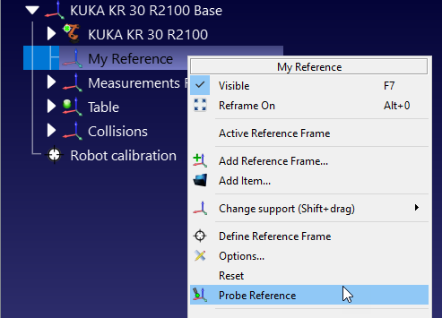
You should then probe 3 points in the following order:
1.First point in the origin.
2.Second point along the positive X axis.
3.Third point along the positive Y axis.
By properly setting your coordinate system you can program robots remotely. For example, if you have a properly defined fixture, when you want to program a new part you can simply do it from your office or from home without even having to be near your robot.
Teach Curves in Motion
You can create a curves, targets and coordinate systems on a moving object if your measurement system supports tracking multiple objects at the same time. This can be done following the same procedure as if they were static.
The main difference is that the moving object needs to be tracked in real time (using a tracker or reflective targets). For example, if you use the Creaform C-Track measurement system you should specify the model in the part reference section and link it to the coordinate system it represents.
The correct dependency of coordinate systems and objects needs to be defined in RoboDK so you can define new coordinate systems relative to your moving target.
This method of programming parts may not be as accurate as when the parts are static.
Settings
This section describes the TwinTrack settings that allow you to better customize the default behavior of the TwinTrack actions.
Select TwinTrack ➔ Settings to open the settings window shown in the following image.
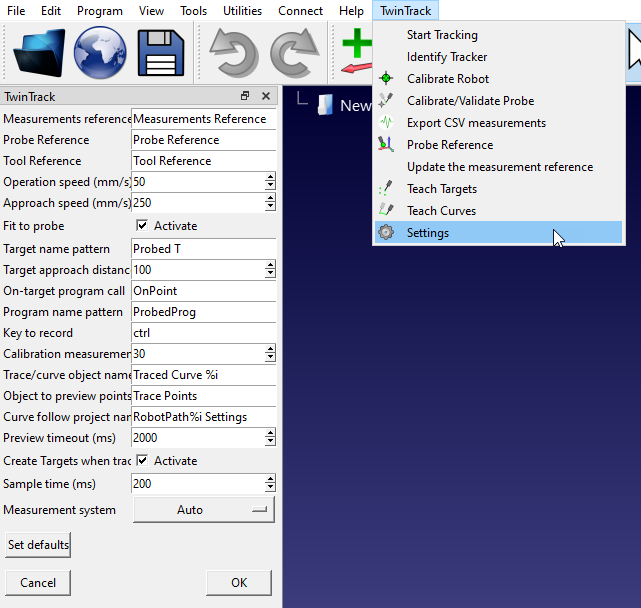
Among other things, you can change the default names used to display the handheld device and the reference frames. You can also customize the approach speed approach distance.
Program Filtering
Once the robot has been calibrated, we need to make sure we generate filtered programs or account for calibrated robot parameters to make sure we take advantage of the robot calibration.
We should follow one and only one of the following methods to program robots accurately after calibration:
1.Use RoboDK for Offline Programming to generate accurate programs (generated programs are already filtered). This is the recommended offline programming option for optimal accuracy results.
2.Calibrate robot controller parameters (such as link lengths, DH-DHM parameters and/or mastering parameters).
Accurate Offline Programming
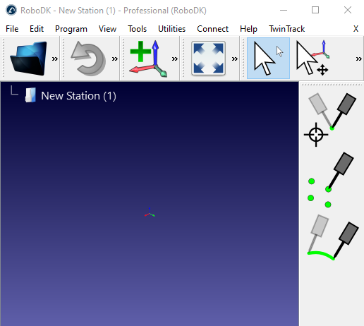
When a robot has been calibrated with RoboDK we have the option to activate accurate kinematics by right clicking the robot and selecting Use accurate kinematics.
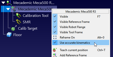
If accuracy is active, we will see a green dot, if it is not active, we will see a red dot.
This is the recommended option to have optimal accuracy results. With the robot accuracy option activated in RoboDK, all programs generated by RoboDK will be automatically filtered. This means that all Cartesian coordinates will be slightly modified to compensate robot errors.
This is the most suitable option if you are planning to use your robots for robot machining, program robots from NC files or use any of RoboDK’s supported CAD/CAM plugins.
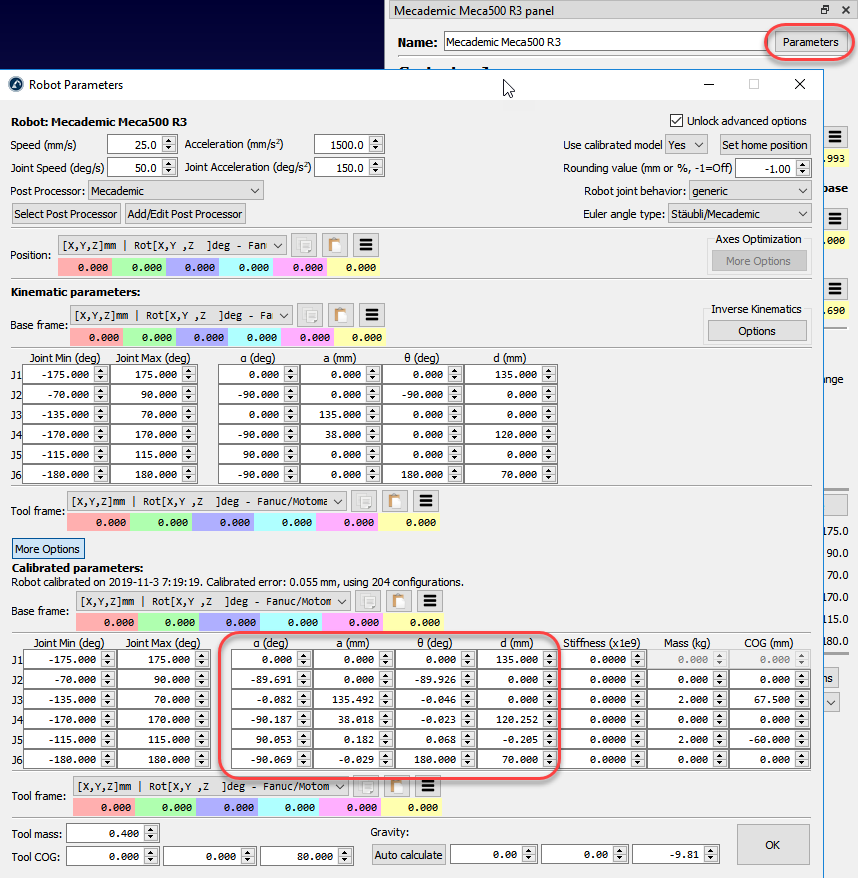
Calibrate robot parameters
You can access the calibrated parameters in the Parameters menu once a robot has been calibrated. Some robot controllers allow modifying certain robot parameters.
Reference frame and tool frame
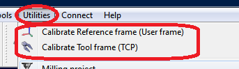
RoboDK provides some utilities to calibrate reference frames and tool frames. These tools can be accessed from Utilities➔Calibrate Reference frame and Utilities➔Calibrate Tool frame respectively.
To calibrate a reference frame or a tool that has not been automatically calibrated (also known as User frame and TCP respectively) we need some robot configurations touching 3 or more points, these robot configurations can either be joint values or Cartesian coordinates (with orientation data in some cases). It is recommended to use the joint values instead of the Cartesian coordinates as it is easier to check the real robot configuration in RoboDK (by copy-pasting the robot joints to the RoboDK main screen).
Tool calibration
Select Utilities➔Calibrate tool to calibrate the TCP using RoboDK. We can use as many points as desired, using different orientations. More points and larger orientation changes is better as we will get a better estimate of the TCP as well as a good estimate of the TCP error.
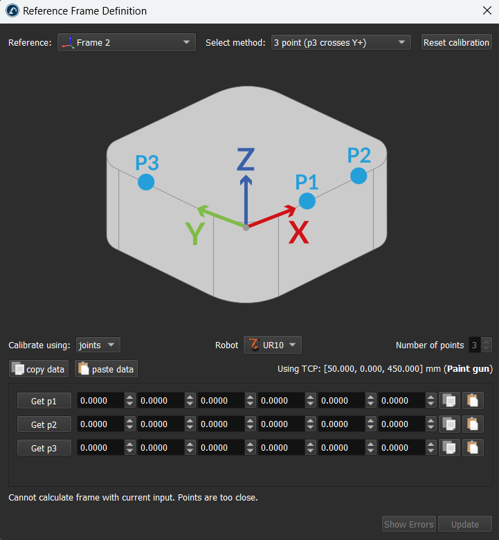
Reference frame calibration
Select Utilities➔Calibrate reference to calibrate a reference frame. It is possible to set a reference frame using different methods. In the example of the figure, a reference frame is defined by three points: point 1 and 2 define the X axis direction and point 3 defines the positive Y axis.
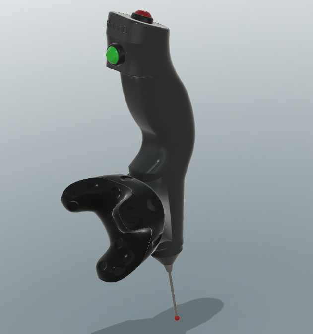
Custom TwinTrack Probe
This section shows how you can build your custom TwinTrack Probe to teach robots by demonstration. A custom probe allows you to make your robots mimic the manufacturing operations taught by a human.
Hardware components
The following list of hardware components allow you to build a custom probe to be used with RoboDK TwinTrack.
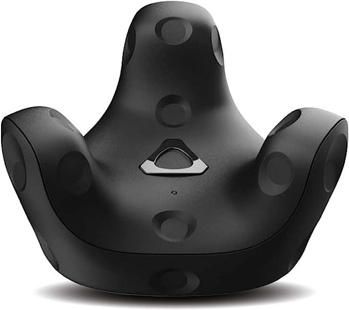
1.One HTC Vive Tracker (any version supported, 3.0 recommended): HTC Vive Tracker 3 On Amazon. Price estimate: 200 EUR.
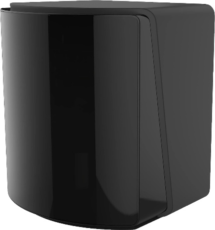
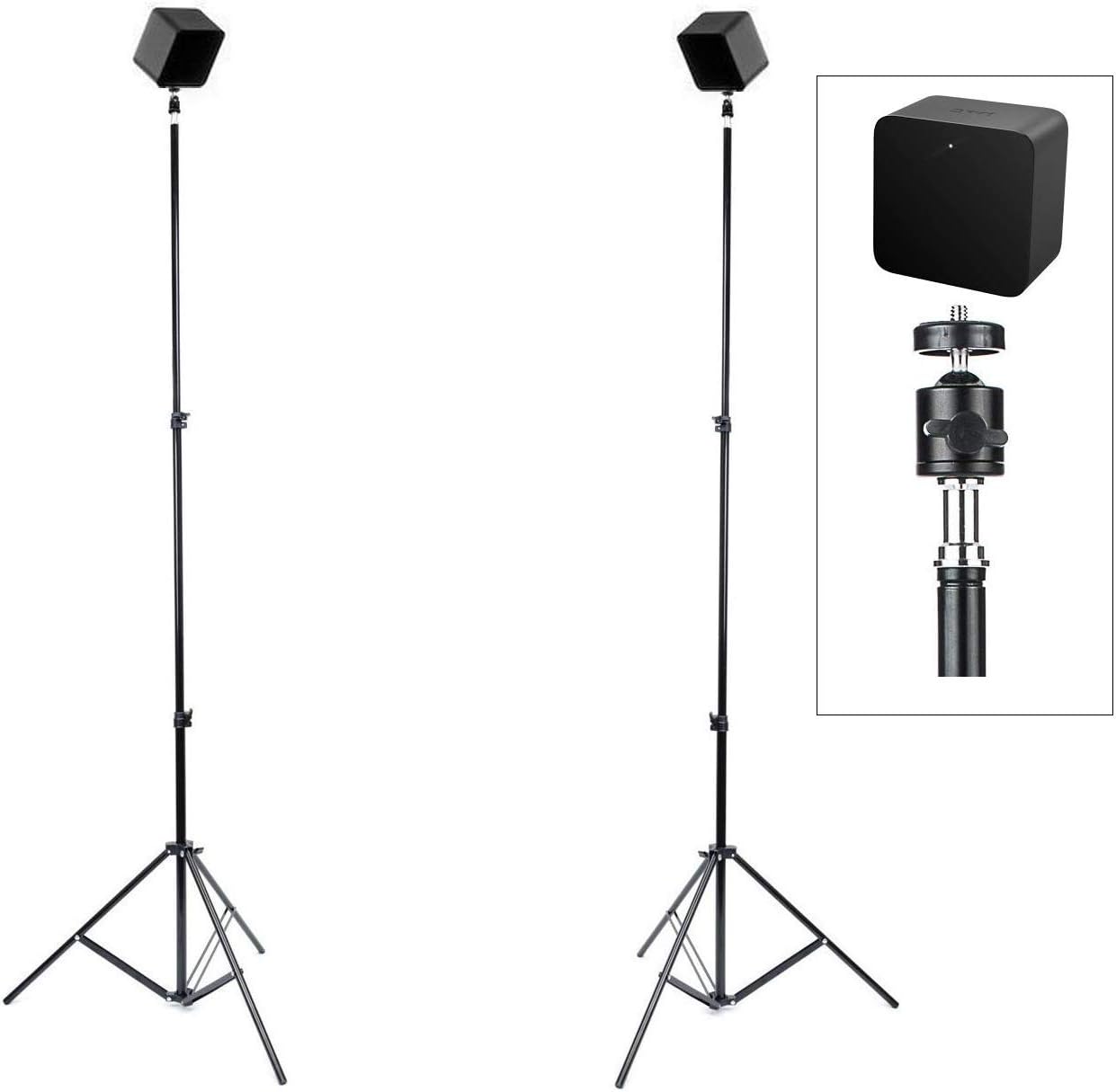
2.Two Valve Index Base stations. Actually any version should work as long as it is compatible with the corresponding HTV Vive Tracker. Valve Base stations on Amazon. Price estimate: 500 EUR for both units.
3.Two tripods for the Valve Base stations. Sample part on Amazon. Price estimate: 100 EUR.
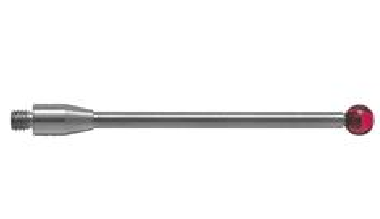
4.One Renishaw ruby ball with 40 mm length and 4 mm diameter. Such as the A-5003-0060. Price estimate: 80 EUR.
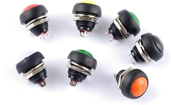
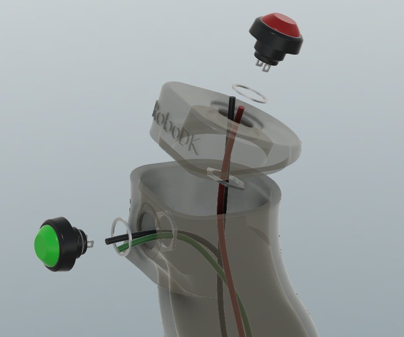
5.Two Push button switches, one red and one green, 12 mm diameter. Pressing the button powers on (closes the circuit), releasing the button powers off (open circuit): Example product on Amazon. Price estimate: 15 EUR.
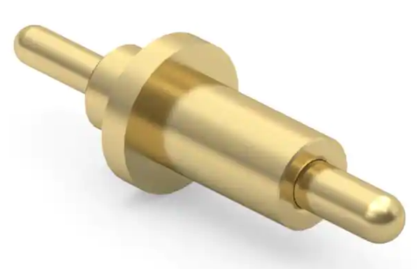
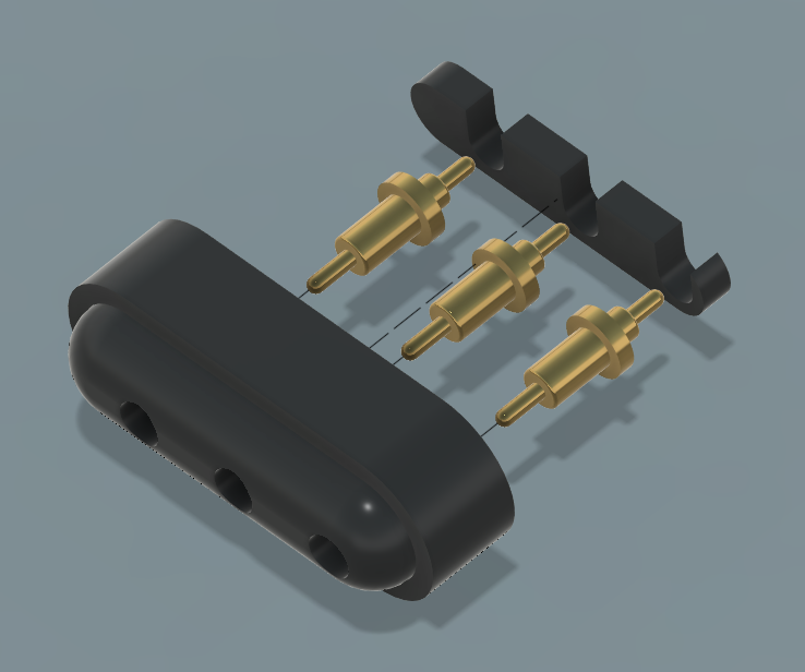
6.Three Spring loaded pogo pins 0856-0-15-20-82-14-11-0 (3 units). Sample product from DigiKey . Price estimate: 20 EUR.
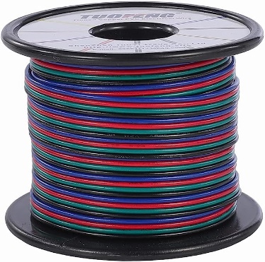
7.Electric wire to connect the switches (less than 1m). Sample order on Amazon. Price estimate: 25 EUR.
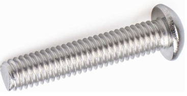
8.One button head socket cap screw ¼-20 x 1”: Sample product on Amazonopen. Price estimate: 10 EUR.
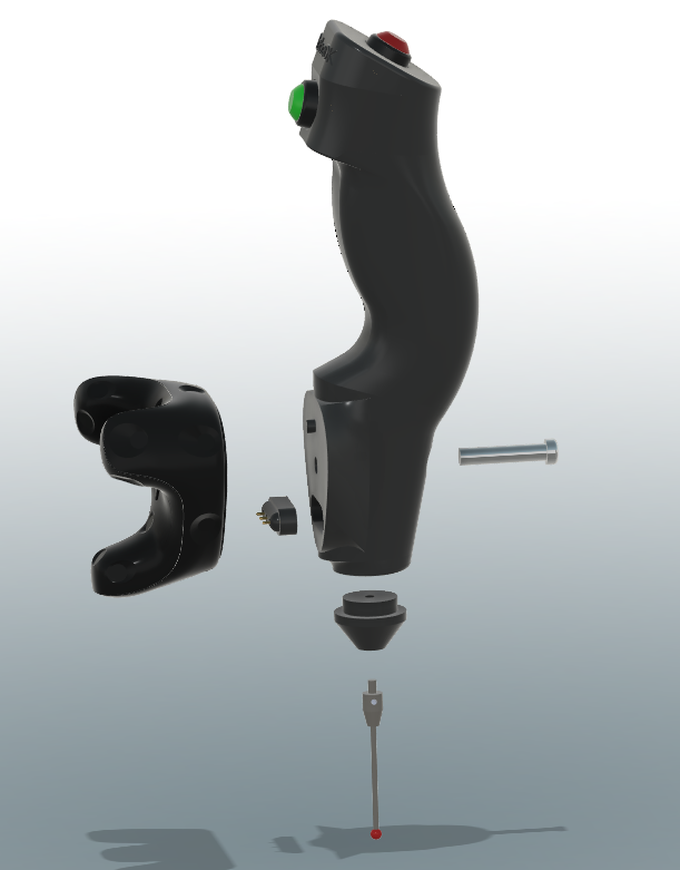
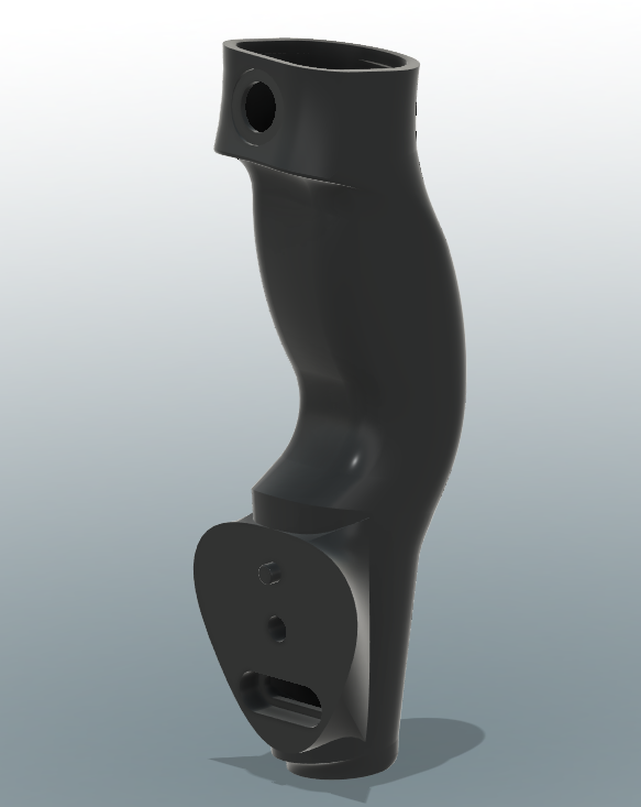
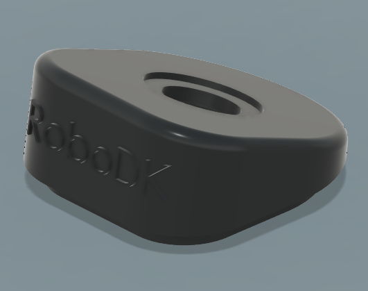
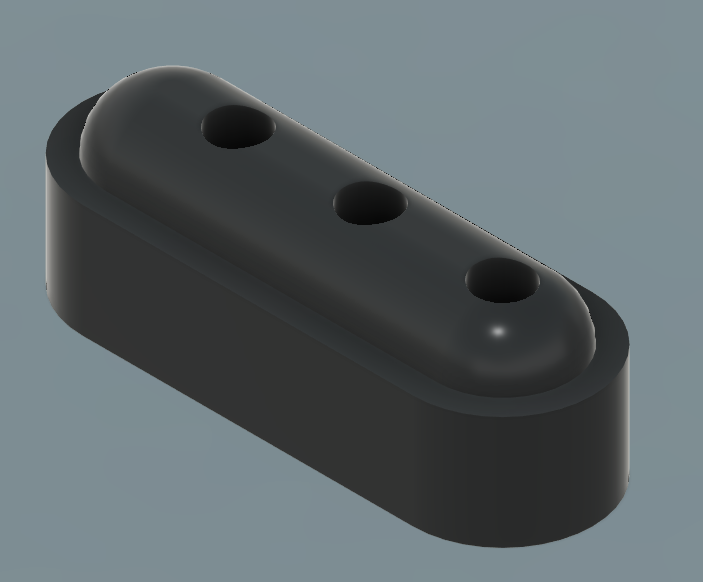
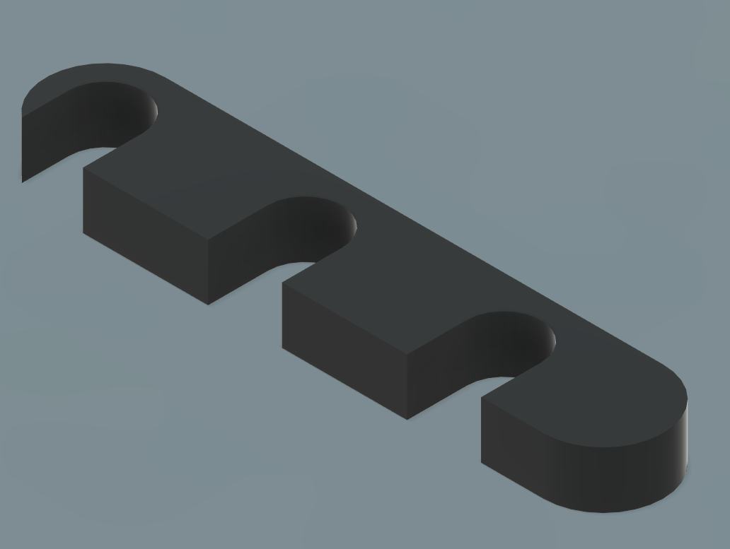
9.Five 3D printed parts, the main body, the probe holder, the top probe, the tracker connector and the connector cap. You can download the 3D printed parts required to build the TwinTrack probe here. The 3D printed parts of the TwinTrack probe are also available on GrabCad and Thinginverse.

Probe Assembly
This section explains how you can assemble the probe for RoboDK TwinTrack. You’ll need the parts required to build the probe described in the previous section. You’ll also need a soldering iron kit.
Follow these steps to assemble the probe:
1.Assemble the connector as follow and glue the printed pieces together.
2.Install the wires inside the main body and through the top piece as shown in the following image. Note that the ground wire is connected to both switches.
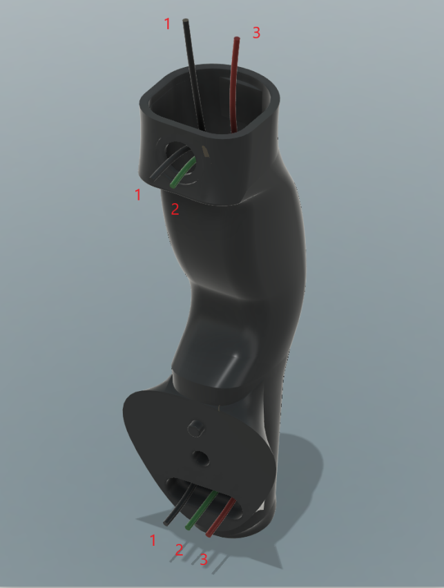
3.Connect the wires to the switches. The 2 pairs of wires should go through the switch nuts. Also, the wire of the red switch should go through the top part. You should then solder the switches (in that order).
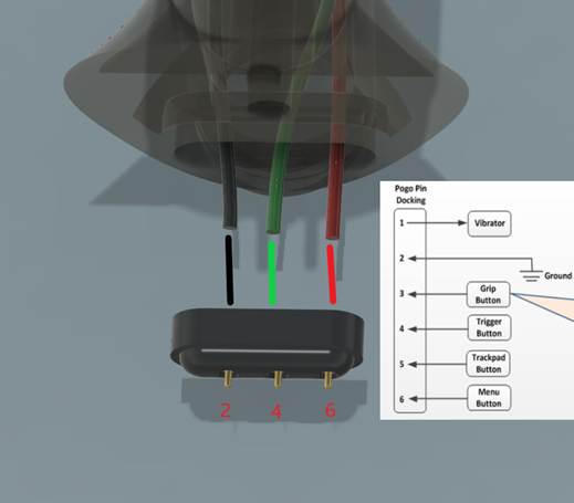
4.Solder the connector to the correct wires. Make sure to place the cables on the right connectors.
5.Assemble the rest of the probe as shown in the following image.