Thread Rating:
  • 0 Vote(s) - 0 Average
  • 1
  • 2
  • 3
  • 4
  • 5

Add folders to robot tools

#1
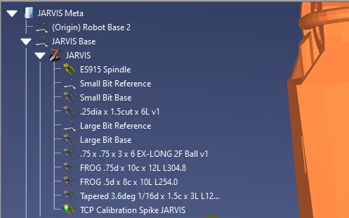
Having the ability to make folders for different tools would be a great way to keep things organized for a milling/machining robot. This is just a small and developing list of tools, but it would be great to make "Flat," "tapered," "ball," etc folders to organize the tools and de-clutter the tree a little bit.

The advantage of this vs exporting different tools into a library to import later is simply speed and efficiency.
Having all of the tools preloaded into the workstation, just organized by folders makes for quick tool assignment for tool path programming. I use Fusion360, as well as Vectric Aspire to generate toolpaths. While Fusion360 can export tool data into RoboDk via add-on, Aspire does not have the proper post-processors or add-ons to do that. So toolpaths get generated in Aspire and uploaded into RoboDK as G-Code, then turned into Python with appropriate TCP configurations for our Kuka KRC2 to process.

Thanks.


#2
I did a quick test and having tools in folders seems to work although you may see unexpected results as tools were designed to work directly attached to robots.

For what I see you can choose these tools from the robot panel.

If you try to drag and drop a folder into a robot within the tree it won't allow you, but you can cut/paste a folder. You can also cut/paste tools inside that folder as shown in the following image:
   

Nice suggestion by the way! If you can tell us a bit more maybe we can create an add-in in RoboDK to easily create or edit tools based on the description.
#3
   
Oh nice. Yeah, that helps a lot. I'll just need to play with it a bit to see if I encounter any problems with this.

I like your latest machining tools utilities update a LOT. I set 2 base locations as references (large bit base / small bit base) and made them "tools" so I can simply (create tool > select appropriate reference tool base > insert overall tool length > click "create") to get a perfectly placed TCP every time.

Something that could make that a little bit more convenient, is being able to select reference frames for the "short" and "long" tool references, so I dont have to turn my base tool references into tools before being able to use them as a base reference for the new created tool lengths.  

The ability to have at least a simple graphics/STL tool generator and/or upload option to attach to the newly created tool would be amazing. That way, not only can you create a new tool with TCP using the machining tool utilities, but also generate/attach a visual aid for the tool too.
A tool generator just doing something simple like taking tool overall length, tool diameter, and cutting length to make a 2 tone cylinder shape that starts at the reference point as silver, and extends to the TCP, representing the cutting length with the gold color. Or even make it to where the user can select which colors they want for higher contrast capabilities depending on their workstation environment.

Sure, having the tool be represented with a body is not "necessary" so long as you can see the TCP, but being able to see the tool profile accurately proportioned makes it easier to detect small unintended collisions when swarfing or working on undercuts. Plus, the visual indicator of the tool being used is just another nice step to insure the intended tool is selected. That color coding option would be great for that. Could make all of the roughing tools have a red tip, for example, and finishing tools be blue or gold. It would be fun.


Users browsing this thread:
1 Guest(s)