03-21-2022, 09:10 PM
I have a (circular) set of XYZIJK node data points and have imported them into a RoboDK curve follow project. The points should make a complete circle under a laser head using mostly J6 to rotate the points of the part through the laser. When I clicked the the update button it fails and when I run the simulate I see the project is moving correctly as expected until the X of the tool is pointing straight down. At this point the robot starts rotating around the tool X and swings until the robot has taken much different pose nearly 180 degrees. The part then finishes but it does so using the remaining expected J6 motion.
If I pull the slider back to where it starts this rotation I can manually slide the J6 slider and see it can complete the motion from the original pose, what can I do to hold a pose in a curve follow project. Why would it begin to rotate around Tool X when it has plenty of stroke left in J4,J5 and especially J6 I do not understand the path planner I would like for it to complete the path in the original robot configuration.
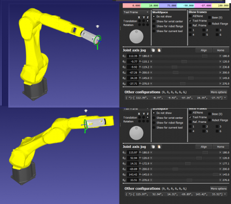
This picture shows the initial pose in the upper area and the new unexpected pose in the lower area. Both of them have 180 deg plus to finish the rotation in J6.

My expectation is the location of each move would be something like
ROBOT_JOINTS : TOOL : NODE_DATA_POINT(n) = FRAME_LASER : ORIENTATION_POS
Once that is established for the first point NODE_DATA_POINT[1] the ORIENTATION_POS would be maintained as we process the remainder of the NODE_DATA_POINT[++].
If I pull the slider back to where it starts this rotation I can manually slide the J6 slider and see it can complete the motion from the original pose, what can I do to hold a pose in a curve follow project. Why would it begin to rotate around Tool X when it has plenty of stroke left in J4,J5 and especially J6 I do not understand the path planner I would like for it to complete the path in the original robot configuration.
This picture shows the initial pose in the upper area and the new unexpected pose in the lower area. Both of them have 180 deg plus to finish the rotation in J6.
My expectation is the location of each move would be something like
ROBOT_JOINTS : TOOL : NODE_DATA_POINT(n) = FRAME_LASER : ORIENTATION_POS
Once that is established for the first point NODE_DATA_POINT[1] the ORIENTATION_POS would be maintained as we process the remainder of the NODE_DATA_POINT[++].


