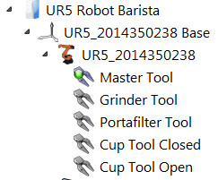
Up until now, I have been using the RoboDK GUI to set up my tooling by importing the tool geometry as an STL file, adjusting the TCP and location of the tool relative to the robot tool flange as necessary, and then saving it as a '.tool' file so the information is preserved. When pulled into a new station, I end up with something like this:

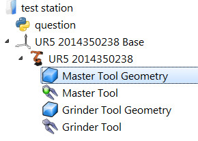
I am now trying to do the same thing using Python - that is, taking the raw tool geometry, and then adjusting the TCP and location of the tool geometry relative to the robot tool flange. The problem is that unlike the previous method, what I end up with in my station tree is one item that is the geometry of the tool, and another item that is the TCP:

Is this the way that the AddTool() function is intended to be used? The problem is that I cannot now delete the geometry items without the tool geometry disappearing. I have attached a simple station that contains the code I have been testing in the hope it helps - note that the PATH variable in question.py will need to be changed if the archive is not unzipped into the C:/RoboDK/User location.
I am now trying to do the same thing using Python - that is, taking the raw tool geometry, and then adjusting the TCP and location of the tool geometry relative to the robot tool flange. The problem is that unlike the previous method, what I end up with in my station tree is one item that is the geometry of the tool, and another item that is the TCP:
Is this the way that the AddTool() function is intended to be used? The problem is that I cannot now delete the geometry items without the tool geometry disappearing. I have attached a simple station that contains the code I have been testing in the hope it helps - note that the PATH variable in question.py will need to be changed if the archive is not unzipped into the C:/RoboDK/User location.


