02-19-2020, 10:01 PM
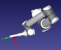
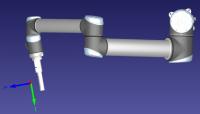
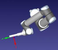
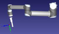
After updating the kinematics for my UR10 using a program created on the teach pendant and the UR_LoadControllerKinematics.py script, I noticed that the position of the tool geometry is now shifting relative to the robot flange as the robot moves. The shift seems to occur whenever any of the robot joints are changed, however it is particularly noticeable for joints 4 and 5. Below are a few screenshots that show the position of the tool before and after executing a move program first with the default kinematics, and then with the updated kinematics enabled. I have also attached the station file that the screenshots were taken from.
Default kinematics:


Controller kinematics:


Is there any way to fix this so that the tool will maintain a consistent distance and rotation with respect to the robot flange? If not, how will this affect the collision detection feature in RoboDK? I am currently using RoboDK to control a real UR10 for a nondestructive inspection project which requires the robot to move the tool along the surface of a part while maintaining a consistent standoff distance of roughly 1 inch. The ability to add targets on the surface of an object and the automatic collision detection feature were two of the main reasons I chose to use RoboDK, but the fact that the tool appears to be shifting by an inch or more as the robot moves makes the software unusable for my purposes. Any suggestions on how to resolve this issue would be greatly appreciated.
Default kinematics:
Controller kinematics:
Is there any way to fix this so that the tool will maintain a consistent distance and rotation with respect to the robot flange? If not, how will this affect the collision detection feature in RoboDK? I am currently using RoboDK to control a real UR10 for a nondestructive inspection project which requires the robot to move the tool along the surface of a part while maintaining a consistent standoff distance of roughly 1 inch. The ability to add targets on the surface of an object and the automatic collision detection feature were two of the main reasons I chose to use RoboDK, but the fact that the tool appears to be shifting by an inch or more as the robot moves makes the software unusable for my purposes. Any suggestions on how to resolve this issue would be greatly appreciated.


