05-01-2020, 10:40 PM
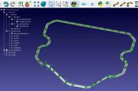
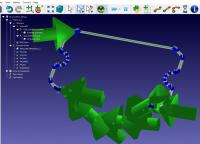
When selecting curves, the direction arrows and the new path unit vectors and spheres have drastically different size scales, making it impossible to see what is being selected. Need to be able to see the white arrows and the green arrows at the same time, as well as highlighted line segments.
Using + and - key shows issue.
At this scale, the green path direction arrows are easy to see, but the blue curve points and white unit vectors are too small to see.

At this scale, the white unit vectors are just visible from the blue curve points, but the green path arrows are so large that they obscure the view of the line segments being selected.

Example STEP file showing geometric surface attached.
Refer to thread Tool-Z-rotation-along-a-curve for RDK station file.
Using + and - key shows issue.
At this scale, the green path direction arrows are easy to see, but the blue curve points and white unit vectors are too small to see.
At this scale, the white unit vectors are just visible from the blue curve points, but the green path arrows are so large that they obscure the view of the line segments being selected.
Example STEP file showing geometric surface attached.
Refer to thread Tool-Z-rotation-along-a-curve for RDK station file.


