Thread Rating:
  • 0 Vote(s) - 0 Average
  • 1
  • 2
  • 3
  • 4
  • 5

Not enough valid calibration points

#1
I'm trying to calibrate a Kuka KR200-3 comp US arm. I've run through the calibration program several times and keep coming up with the error "Not enough valid calibration points." I tried with 60 and 70 points, same result:
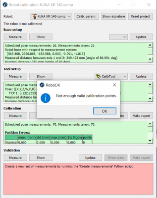
   

I've attached my robodk project here, I'm using a KR140 comp because the KR200 is not in the library, but they have the same geometry:

pf0008_kr_1403_comp_en.pdf (kuka.com)
pf0009_kr_2003_comp_en.pdf (kuka.com)

Do I need to do 80 points? 100? I have a limited work space, maybe that affects things.

I have a KRC2 ed05 controller and can't get it to connect via ethernet so I'd rather not keep blindly doing tests, as each manual run takes me 2 hours.

Any ideas are appreciated, thanks!


Attached Files
.rdk   Kuka22.rdk (Size: 1.38 MB / Downloads: 217)
#2
Well, I tried with 85 points with the same result. Glad I didn't do 100, I don't feel that doing more points is actually the answer, maybe I have a problem with my RDK station. I'll get back on this tomorrow.
#3
The problem with your project is that no measurements are within the default tolerance of 20 mm to consider a measurement valid. This could be for many reasons. In your case, it is because of invalid measurements for pose orientation (all measurements are 0 for WPR values).

It looks like you selected 6 DOF measurements (poses) when you started the calibration. If you use a laser tracker you should select 3 DOF measurements unless you use a laser tracker that supports pose measurements (and the RoboDK driver for the laser tracker also supports it).

To fix that and to take advantage of the measurements you already took, I exported all measurement tables and deleted the pose orientation information for the measurements and the tool (columns 10-12 and 16-18). You can edit these files using Excel and import the tables again. Another option would be to start over all measurements. See the project attached.

I believe the base setup and tool setup were properly completed. Can you confirm you placed the target in this location?
   

Did you place the laser tracker on top of the rotary table? Did you move it?

I noticed you used the Set measurement reference option. I strongly recommend you to not use this option when you run your first calibration as it can lead to confusion. You should simply run the calibration procedure without setting any references.

Was this robot working properly before you took the measurements? (for example, properly mastered)
The robot model is different, however, I checked the DH table and everything looks correct (all parameters match the spec sheet of your robot).

For some reason, the measurements are still off by 100-200 mm compared to the nominal expected values. We should see 5-10 mm at most for a robot like this. Our default tolerance to consider a measurement valid is quite permissive at 20 mm (it can be increased in Tools-Options, then select Accuracy tab). 

One option to troubleshoot is to open the measurements table with a spreadsheet, copy the measurement values and paste them in RoboDK. I did this procedure for the first 5 points for the project attached. You should see the real measured values as you scroll through the scheduled measurements.

If we are unable to find the source of the problem, I would re-run the calibration without using the Set measurement reference option (I removed it for the project attached).


Attached Files
.rdk   Kuka22-v2.rdk (Size: 1.34 MB / Downloads: 194)
#4
Thanks Albert, the DOF makes sense! I was reading through the calibration manual again and realized I had everything wrt the measurements reference rather than wrt the robot base frame. I'll rerun it with 3dof tomorrow, without the set reference.

This arm had lost mastering and I don't have a mastering tool so I just eyeballed the white marks. Maybe that's the major error, I can use a ballpoint pen and clean that up tomorrow as well.

You're correct that the SMR is in that location (calib tool 1), I'll update this thread tomorrow with the results of all these changes.
#5
(07-29-2022, 09:22 PM)Albert Wrote:  re-run the calibration without using the Set measurement reference option

I reran the calibration with your suggestions, but with the same result. 3DOF, no measurement reference, and I mastered the robot with a dial indicator before resetting and recreating the calibration program.

For kicks, I tried rearranging all the frames to be WRT the base frame. Same thing! Here's the rdk file.

Two strange things with this as well: 

1) this "Follow Target" check mark option just makes the tracker abandon the measurement and point to a position a few degrees right of wherever it's looking. It has to be checked to make the tracker actually measure anything. Must not be for my situation but it suddenly started being unchecked every time I made a new calibration operation. (see attached followtracker.png)

2) Another strange "all of a sudden" thing is when I finished the last calibration, it flipped my tool around. Did it update my tool based on the calibration measurements? Maybe I should just take the tool off and do this right on the flange?  (see attached flip.png)


Attached Files Thumbnail(s)
   
Image(s)
   

.rdk   Kuka22-3.rdk (Size: 1.38 MB / Downloads: 184)
#6
Something is quite off regarding the kinematic model. I would double check that the robot kinematics is correct.

We can validate if the robot is properly modeled in RoboDK by simply checking a list of points. Make sure you remove the tool and the base frame so that the tool is the robot flange and the base frame is the robot base. You can then validate for any joint values if the robot pose is correct (RoboDK pose vs KUKA teach pendant pose).

The tool is flipped because the robot model is quite off.

Also, once you are done with the base setup and tool setup, if you check "Follow target" the laser tracker should point at the target/SMR. This accuracy should be within 2-5 mm. We are currently seeing an average position error of 170 mm. This is far too much and it should be in the order of 5 mm. This is probably because of different nominal kinematics. I would double check that the robot arm is correct. You could even measure the distance between links (roughly with measurement tape) to make sure nobody changed any robot links, we have seen this with used robots.
#7
Makes sense about the Follow Target option! So it's just shooting to where it SHOULD be, and that happens to be 6 inches away.

The 140 dimensions match what I actually have here, as close as my tape measure can get. And the robodk robot model dimensions match as well.

I remade the cell without a spindle tool and re-downloaded the 140 from the library, I'll run it today with no tool (also removed from robot arm).

After I run tool setup, it asks me if i want to update the tool frame (or calibration tool frame, I don't remember), default is Yes. I just hit yes, maybe I shouldn't have?
#8
Working with a new-from-scratch rdk cell.

I removed the tool and just ran the base/tool calibration. As you can see in the screenshot, the program added another "CalibTool 1" frame (circled in red) in addition to the one I had made on the flange, but it's 100mm or so out from the tool flange. I measured my robot arm and it matches the dimensions of the KR140 model in the rdk program. (Just moving a reference frame around to measure distances)

Unrelated to that, I saved and closed, opened again, and the bonus CalibTool 1 was now moved back to the flange. With a shrug I tried creating calibration points, but the python errored (see attachment). I tried deleting the calibration and redoing it by importing the measurements, but the result is the same python error.


Any idea what else is wrong?

On a whim I tried deleting the CalibTool 1 frame I had made, and that let the python script run. Had a bunch of collision errors so I deleted the frame asm and now it's good to go. scrolling through the points, I don't see any collisions likely so I'll run it tomorrow. (out of time for the day)


Attached Files Thumbnail(s)
   

.rdk   kuka22 - no tool.rdk (Size: 1.16 MB / Downloads: 208)
#9
CalibTool 1 is added automatically when you run the Create measurements script.

The laser tracker target was placed at this TCP location:
X=-6.93, Y=-28.67, Z=19.58 mm

Does that make sense?

If so, you can run the calibration procedure. Make sure to not move the laser tracker. The laser tracker should remain in the same location for all measurements.

If you uncheck the option "Follow target", the laser tracker should automatically point to your target.
#10
(08-02-2022, 08:07 AM)Albert Wrote: The laser tracker target was placed at this TCP location:
X=-6.93, Y=-28.67,  Z=19.58 mm

Looks about right! Just odd that the reference frame is 100mm further out temporarily (in appearance only)


Attached Files Thumbnail(s)


Users browsing this thread:
2 Guest(s)