It’s hard to get your head around robot rotations, isn’t it? Euler Angles are a pain in the neck. Here’s the essential primer to take away the pain.
Orientations! They just make me want to tear my hair out. If you have ever had to program a robot’s end pose using coordinates and rotations, you’ll know what I’m talking about.
At first glance, setting the pose of your robot’s end effector seems simple, doesn’t it?
You simply say “I want to move the robot’s tool to this location and I want it to point in this direction.”
Intuitively, you know exactly what orientation you want the tool to have. However, when it comes to describing the orientation using precise numbers, suddenly this simple task becomes a mess of confusion.
Why Robot Orientations are Hard to Understand
It’s easy to describe the X, Y, Z (translational) coordinates of a robot’s tool.
To describe a translation, you simply enter the coordinates — e.g. Point[X, Y, Z] = [100, 1000, 1500] mm — and there is only one location that this could refer to, assuming that you are using the same base reference. It can only mean 100 mm along the X-axis, 1 meter along the Y-axis and 1.5 meters along the Z-axis.
But, how do you describe the orientation of the tool?
You could say:
Rotation[XYZ] = [5, 45, 15]°
however, you could equally say (rounding the numbers)
Rot[XY’Z”] = [-7.9, 44.7, 16.2]°
or
Rot[ZY’Z”] = [7.9, 45.2, 5.0]°
or even
Quaternion[q1-q4] = [0.9, -0.1, 0.4, 0.1]
All of these refer to exactly the same orientation!
What makes it even more mind-bending is that different robot manufacturers use different conventions. It can all become a bit of a headache, even when you are familiar with 3D geometry.
The Problem: We Just Don’t Think in Rotations
The real problem is that we just don’t naturally think in terms of rotations.
We intuitively understand translational coordinates because we use them in our everyday life (e.g. “It’s on the second shelf down, four books from the left.”). However, when we have to describe an orientation, we resort to pointing with our finger and saying “It’s in that direction.”
Unfortunately, robots need more precise information than a vague “it’s over there.”
What we need is a solid understanding of Euler Angles.
What are Euler Angles?
Let’s take a step back and start with the basics.
The most common method for describing robot orientations are Euler Angles. Euler Angles consists of three numbers which each describe a rotation around one axis. There are different Euler Angle conventions depending on the order of rotations.
First, let’s simplify this to a one axis example.
Imagine a compass.
Often the world’s Z-axis refers to the axis that stretches from the sky to the ground. So, you can think of the needle on a compass being a rotation around the Z-axis (named Rot[Z]). When you hold the compass flat in front of you and the arrow points to 135°, it means that North is over your left shoulder so you are currently facing South-East. It doesn’t matter where you locate the compass (on the floor, on your head, etc) if it has the same orientation, the angle will always be 135°.
So far, so simple.
Our compass has only one rotation value (i.e. Rot[Z]) but to describe any 3D orientation we need three values. This is where it starts to get a bit more complicated.
Other methods for describing robot orientations are Quaternions or Poses (4×4 matrices).
Let’s Get Hand’s On
From now on, it will be helpful for you to have an interactive visual aid.
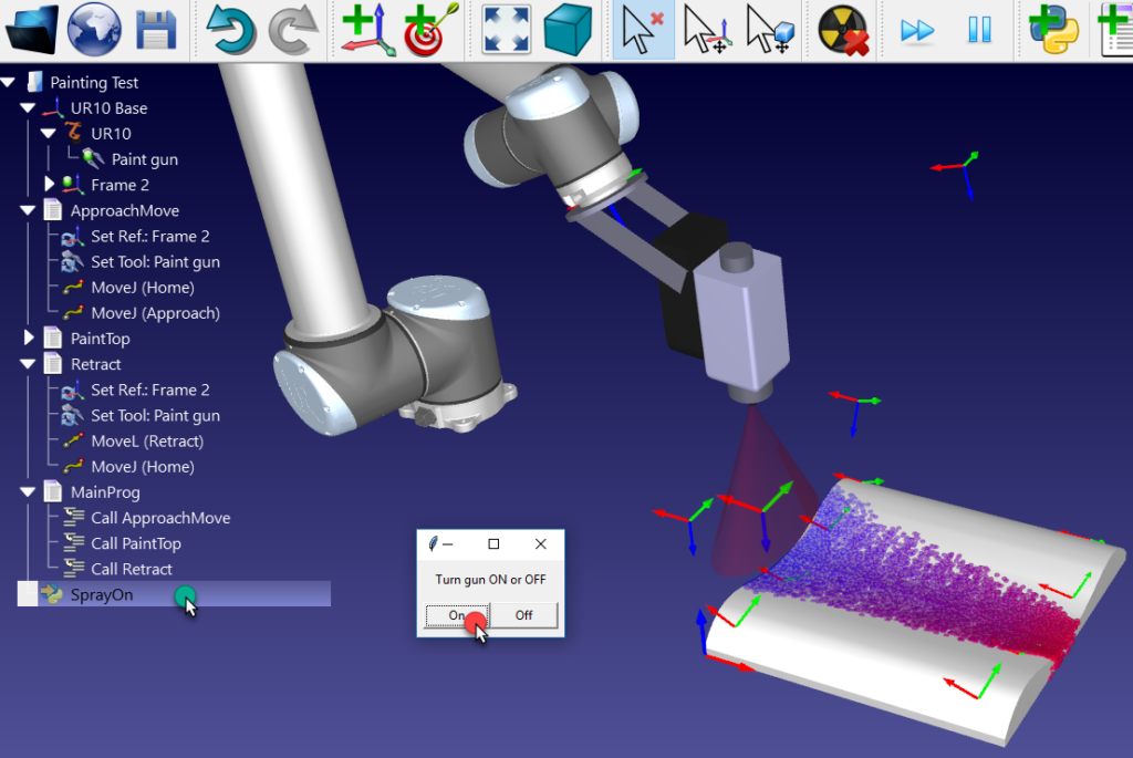
I suggest you download a free copy of RoboDK at this link, which makes it very easy to visualize reference frames and see the resulting coordinates.
Launch RoboDK and create a reference frame using the “Add Reference Frame” button or selecting the option in the Program menu. You should see a red, green and blue frame appear in the middle of the screen.
You can rotate the frame like this: hold down the Alt key, then click and drag one of the curved arrows which appear.
How to Fly a Plane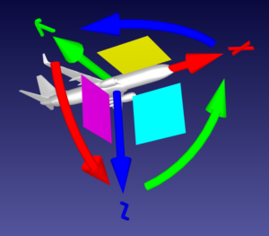

Let’s use the analogy of an aeroplane, as described very clearly on robot-forum.
Imagine the reference frame is a plane. The tip of the straight, red arrow (the X-axis) is the tip of its nose-cone and the straight, green arrow (the Y-axis) is its left wing.
In this case, moving the curved arrows serves the following functions:
- Curved red arrow = Rot[X]: The Roll of the plane, which allows the plane to spin about its horizontal axis.
- Curved green arrow = Rot[Y]: The Pitch of the plane, which points the nose-cone up or down.
- Curved blue arrow = Rot[Z]: The Yaw of the plane, which determines the direction the plane is headed.
If the pilot wanted the plane to turn left and down, gradually, the plane wouldn’t just spin on the Z axis — that’s not how planes work.
Instead, the plane would:
- Pitch its nose-cone down: Rot[Y]
- Roll the plane to the left: -Rot[X]
- Yaw to the left: Rot[Z]
This whole movement would be represented as Rot[XYZ]. Try moving the frame around a bit yourself in RoboDK until you are comfortable with these concepts.
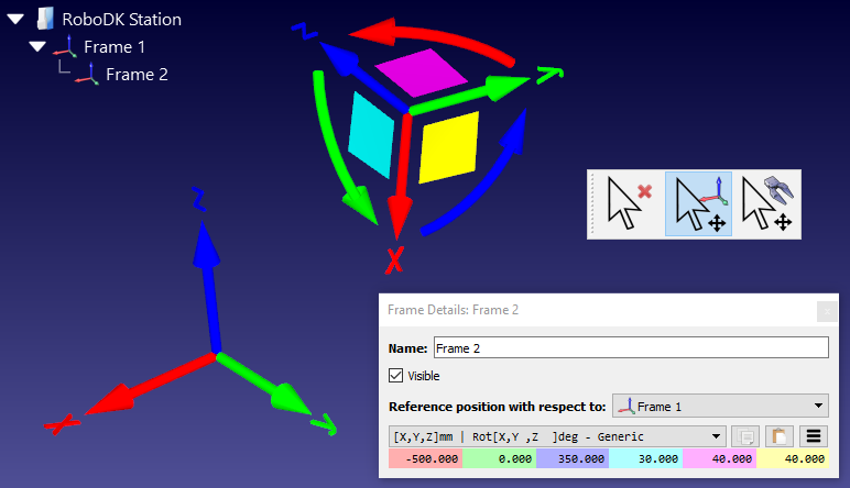
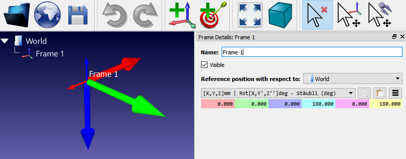
Then, double-click the frame’s name on the top left of the main window to bring up the “Frame Details” panel.
One Orientation, Several Possible Rotations
Using RoboDK, try the following tasks.
Before each task, reset the frame by opening the “hamburger” menu icon (three horizontal lines) in the Frame Details panel and selecting “Reset (set identity)”.
- Select the drop-down menu on top of the coordinates and choose the Stäubli rotation (X->Y’->Z”) instead of Generic.
- Rotate the frame so that blue (Z) is pointing down and red (X) is pointing backwards (i.e. they are both flipped from their starting position and green (Y) is the same as it’s starting position), but only do so by rotating about the Y-axis.
- Reset the frame then move it to the same rotation again. However, this time only use one Z rotation and then one X rotation.
- Reset the frame then move it to the same rotation again. However, this time only use one X rotation and then one Z rotation.
As you can see, there can be more than one way to achieve the same orientation.
The first method we could call it Rot[Y], as it only includes a rotation about the Y-axis. The second method we could call it Rot[Z, X’], as it includes one rotation about the Z-axis and one rotation about the new X-axis. The third we would call Rot[X, Z’]. The prime symbol means the rotation happens with respect to the last movement instead of the static axes.
This is the fundamental concept behind Euler angles. You can rotate a frame to the same orientation in multiple ways by changing the sequence of axes and rotations.
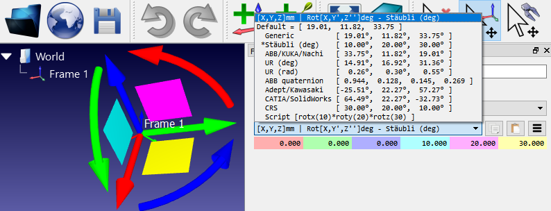
Different robot manufacturers have chosen different combinations of rotations. For example, Stäubli uses an XY’Z” convention, Adept uses a ZY’Z” convention, KUKA uses a ZY’X” convention and Fanuc & Motoman use XYZ convention. On the other hand, ABB uses Quaternion and Universal Robots uses an orientation vector. But all of the conventions can be used to represent any orientation in space.
You’ll find more information in RoboDK’s Documentation.
Test Different Robot Conventions
Hopefully, this is starting to make sense. However, this is only the beginning. To truly master the Euler angles conventions in RoboDK, I find it useful to play around with the software following this guide.
You can see the effect of your rotations in numbers in the light blue, purple and yellow boxes in the “Frame Details” panel.
By default, the Generic XYZ convention is chosen for new reference frames. Try selecting different robot manufacturers from the drop-down menu above the colored boxes. Try entering numerical values into the boxes to see their effects on the reference frame.
For an in-depth tutorial on Euler angles, I can also recommend this page on Mecademic.