Need to use multiple end effectors with your robot? No problem! You can just add a tool changer. But, is it so easy with offline programming? Here’s how to use them in RoboDK.
You’ve picked the perfect end effector for your task from the many tools available on the market. You’ve attached the tool to the robot and added it to RoboDK in under 5 minutes. You’ve then easily programmed the end effector with RoboDK.
Your robot and end effector are working perfectly together.
But then, you run into a problem.
Part of the task requires you to use a different end effector.
“No problem,” you think. “I’ll just add a tool changer.”
But, how do you use a tool changer with offline programming?
This article provides the answer to this common question from our users.
How Tool Changers Are Programmed
Tool changers are quite straightforward to program.
Every tool change follows a sequence which looks more or less like this:
- Move the robot into position at the tool changer.
- Check the signals which indicate that the tool is aligned correctly, if available with your tool changer
- Activate the tool changer.
- Check the signals that show if the tool change was successful, if available with your tool changer.
- Move the robot away.
The exact sequence of control signals will vary depending on your brand and model of tool changer. For example, the pneumatic ATI QC-20 follows the basic sequence described above, while the Schunk SWS requires an extra power-down step to avoid electrical damage. However, the sequence will be very similar with most tool changers.
For offline programming with RoboDK, we can categorize these five steps like this:
- Motion steps — Steps 1 and 5 — You move the robot into position at the tool stand using a combination of joint moves and linear moves in RoboDK.
- Sensor and control steps — Steps 2 to 4 — You write an external function in the robot language which carries out the docking sequence.
Preparing to Add a Tool Changer to RoboDK
There are three things you should prepare before you can use a tool changer with RoboDK.
These are:
1. Ensure Compatibility
Check that your tool changer is compatible with your robot and tool. Make sure that the fittings on the tool match with the fittings on the tool changer, and that the tool changer fits on the end of the robot flange.
Also, calculate the static moment load and ensure that your robot’s payload is higher than the combined weight of the tool changer and heaviest tool.
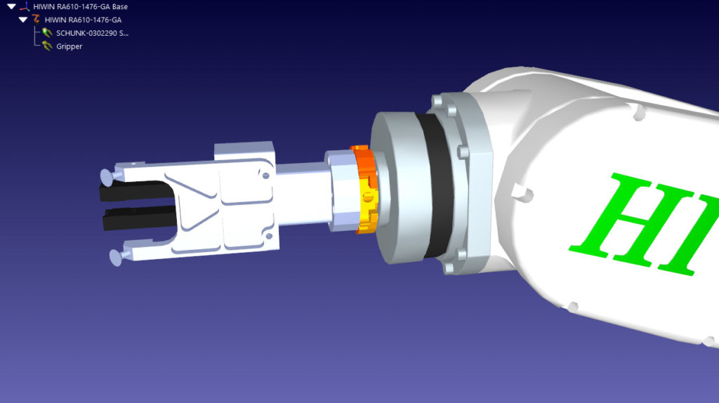
2. Load Tool Changer Models into RoboDK (optional)
If you want to have a visual representation of the tool changer in RoboDK (which is not vital but can be nice) you will need to add it as a CAD file. This involves following almost exactly the same process as you followed to add an end effector to RoboDK.
There are usually two parts to a tool changer:
- The tool stand — This is fixed to the environment and will be represented as an object (or assembly) within RoboDK.
- The tool changer itself — Within RoboDK, this is attached to the robot flange as a tool, just like any other end effector.
3. Create Program Functions for the Tool Changer
You will also need to program one or more functions which activate the tool changer from within your robot program. Again, this is similar to the process for creating functions to control an end effector. However, it is likely to involve a few more steps and be a little more complicated.
In the operating manual for your tool changer, you should find a section titled something like “Coupling Sequence.” This will include a detailed description of the sequence. It can be a good idea to draw a flowchart of the sequence before you write it as code, to ensure you don’t miss any steps.
3 Ways to Use a Tool Changer in RoboDK
Once your preparations are completed, there are three ways that you can use a tool changer in RoboDK. All three of them will be equally effective in controlling the real robotic system. However, some will look more realistic in the simulation than others (and require more work).
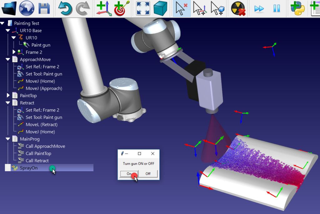
1. The Simplest Way — An Invisible Tool Changer, Stand and Tools
You don’t need to show anything in the simulation to create a functional tool changer. You can just use empty tools to represent both the tool changer and tools. This will create the necessary tool reference frames, but no visual representation of the tool.
You will need to add the following to your simulation:
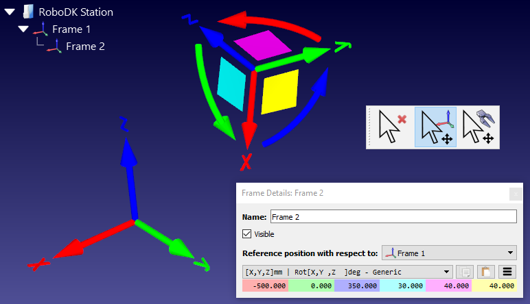
- Target points for each location in your tool changer (Program menu > Teach Target)
- An “empty tool” for each of your tools (Program menu > Add empty tool)
Then, use the following programming sequence to carry out a tool change:
- Move the robot to the target location in your tool changer.
- Select the tool by setting its tool frame (Program menu > Set Tool Frame Instruction).
- Call your tool change function (Program menu > Program Call Instruction)
Simple!
Nothing will change visually in the simulation, but it will work just fine on the real robot.
2. The Half-Visual Way — Create Visual Tools
If you want to add some animation to your simulation, you can introduce visual models of the tool as described above. These tools should all be attached to the robot at its flange, but only one tool (the active tool) should be visible at a time.
Then, you just need to add the following steps to your programming after step 2 above (when you set your new tool frame):
- Hide the old tool (Program menu > Simulation Event Instruction > Hide object/tool)
- Show the new tool (Program menu > Simulation Event Instruction > Show object/tool)
That’s all! Now, the tool will visibly change in the simulation.
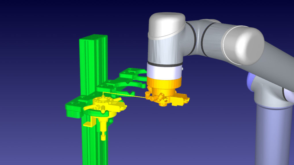
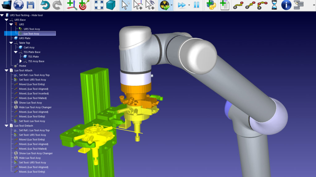
3. The Full Animation Way — Animate Everything
The only thing missing now is to leave the old tool hanging on the tool stand in the simulation. This isn’t necessary from a functional perspective, but it looks cool.
To achieve this, you need to add some more objects to your simulation:
- The tool stand, if you haven’t added it already.
- A “dummy” copy of each tool which you should “hang” at the correct locations on the tool stand.
As with the previous way, all you need to do is hide/show the relevant models at certain points in the simulation.
To pick up a tool from the tool stand, add these instructions to your program:
- Hide the tool attached to the robot flange.
- Show the dummy tool object attached to the tool stand.
To deposit a tool onto the tool stand, add these instructions to your program:
- Hide the dummy tool object attached to the tool stand.
- Show the tool attached to the robot flange.
Where to Find a Working Example
The best way to understand this process is to see it working in action.
Let’s use a real example that user RBE posted on our forum. They were using a tool changer to deposit a tool onto a tool stand. They had programmed the robot to move to the tool stand, then deactivate the tool. But, nothing changed visually in the simulation. The tool was still attached to the robot, and nothing was hanging on the tool stand.
This is a perfect example where the program would work properly on a real robot, but looked wrong in the simulation.
Jeremy (a RoboDK admin) provided a solution to this issue which involved the steps I’ve laid out above. RBE just needed to hide the tool at the same time as they made the dummy tool visible on the tool stand.
Sign up to the forum yourself and you can download Jeremy’s project file to see how was done.
How would a tool changer improve your application? Tell us in the comments below or join the discussion on LinkedIn, Twitter, Facebook, Instagram or in the RoboDK Forum.