Feed rate is a key concept in machining and refers to the speed at which your cutting tool advances through the workpiece. Calculating the right feed rate can be complicated, as it depends on your workpiece material, tool geometry, machine rigidity, and your desired finish quality.
How do you choose the right feed rate for your specific machining operation?
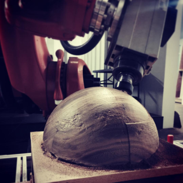
In this guide, we introduce the fundamentals for calculating your optimal feed rate. We also discuss robot machining, along with some factors that determine the ideal feed rate for CNC milling, both with and without a robot.
How Is Feed Rate in Machining Expressed?
The feed rate of a milling operation is usually expressed as feed per minute (vf), sometimes referred to as “table feed”. However, this is not the only way to describe the feed rate, with different terms used for different types of machining.

The table below shows three distinct values used to express feed rate:
| Feed Value | Units | What It Describes | Where You’ll Use It |
|---|---|---|---|
| Feed per tooth (fz) | mm/tooth or in/tooth | Material removed by each cutting edge per revolution | Milling, from tool manufacturer data |
| Feed per revolution (fn) | mm/rev or in/rev | Distance the tool advances in one spindle revolution | Most common for CNC turning |
| Feed per minute (vf) | mm/min or in/min (IPM) | Linear speed of the tool through the workpiece | Most common for CNC milling |
Which value should you use? With robotic milling, feed per minute is probably the most common. However, if you need a different value, it’s easy to convert between them.
How to Calculate the Optimal Feed Rate for Milling
It’s important to calculate the right feed rate for a milling operation. If you move the tool too fast, it can break the tool and ruin the surface finish of your workpiece. Moving it too slowly can increase long-term wear on the tool and also reduce the throughput of your operation.
Here are two simple steps for calculating the optimal feed rate for a milling operation:
Step 1: Calculate Your Spindle Speed
Before you can calculate your feed rate, you need to calculate the speed of the milling spindle in revolutions per minute (RPM).
The equation for spindle speed is:
spindle speed in RPM = (surface speed in m/min × 1000) ÷ (π × tool diameter in mm)
To find the appropriate surface speed for your setup, first start with the tool manufacturer’s data for recommended surface speeds and feed per tooth.
feed rate in mm/min = spindle speed in RPM × feed per tooth in mm × number of flutes
For example, a 10 mm, 3-flute carbide end mill in aluminum has a recommended surface speed of 300 m/min. This gives a spindle speed of about 9,549 RPM. With a feed per tooth of 0.1 mm, that gives a feed rate of roughly 2,865 mm/min.

Step 2: Adjust for Your Real Cutting Conditions
Although you have calculated the optimal feed rate, the calculation doesn’t end there. At this point, you have a lot of choices to make. Experienced machinists use this optimal rate as a baseline from which to adjust for their specific needs.
Some considerations include:
- Check that your machine can reach the calculated revolutions per minute. If it can’t, run it at its maximum safe speed instead and recalculate the feed rate from the actual RPM.
- Account for radial chip thinning. When your width of cut is below half of the tool diameter, the real chip is thinner than the programmed feed per tooth. You need to raise the feed rate to avoid rubbing.
- Choose between roughing and finishing. During roughing, you’re aiming for maximum material removal, while finishing uses a lower feed and a higher spindle speed to achieve a better surface finish.
- Weigh the speed of cutting against tool life. A stable process is usually more reliable than an aggressive material process that continually breaks tools.
The more experienced you are, the easier it becomes to make these adaptations to the feed rate.
Why Feed Rate Behaves Differently on a Machining Robot
Most guidance on feed rate optimization assumes that you’re using a rigid conventional CNC machine. But, the rise of robotic machining is changing that, introducing a set of factors that affect machining feed rate.
According to robotics research, the stiffness of an industrial robot is usually below 1 N/μm, compared to over 50 N/μm for conventional machine tools. This makes robots much more sensitive to vibrations during milling and affects the maximum achievable feed rate.
Robot path planning also introduces extra factors that can reduce the achievable feed rate if a programmed path would push a joint beyond its limits of speed, acceleration, or jerk. The robot’s path planner has to reduce the feed rate to account for these limits.
Finally, there’s the impact of motion smoothing. Abrupt speed changes can cause unhelpful vibrations in a robot’s flexible structure. Motion planning for robot milling has to prioritize smooth jerk-limited speed profiles to avoid this.
Feed Rate for Robot Machining: Start With the Formula, Then Simulate
How can you ensure the feed rates, approach motions, and clearance planes are suitable for robot milling?
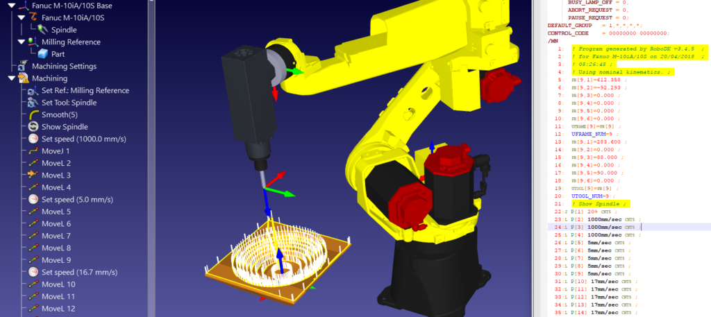
The easiest way to test your robot machining setup is to simulate your toolpaths in a robot simulator before you begin cutting.
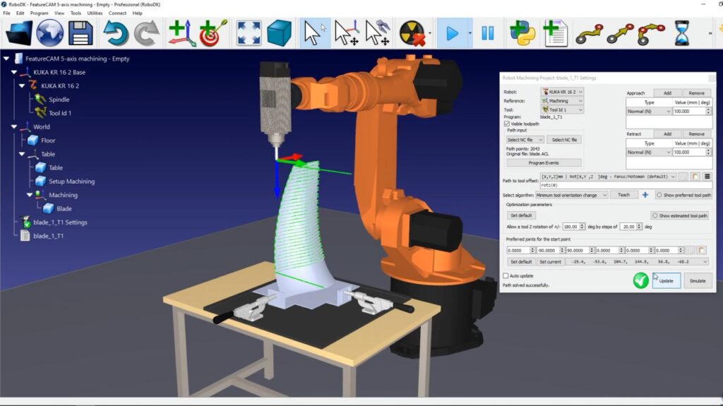
RoboDK-CAM lets you set feed rates, program and test different approach and retract motions, and simulate your full robot machining program before you send the program to your physical robot
For more information, check out the RoboDK CAM product page.
What milling tasks do you have that could benefit from robot machining? Join the discussion on LinkedIn, Twitter, Facebook, Instagram, or in the RoboDK Forum.. Also, check out our extensive video collection and subscribe to the RoboDK YouTube Channel